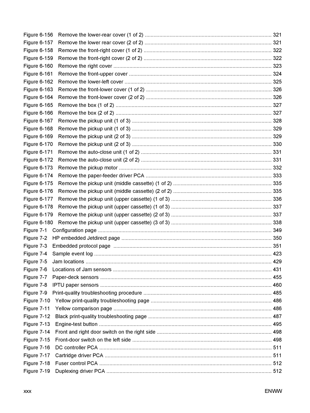
Figure 6-156 Remove the lower-rear cover (1 of 2) .......................................................................................

321

Figure 6-157 Remove the lower rear cover (2 of 2) .......................................................................................

321

Figure 6-158 Remove the front-right cover (1 of 2) ........................................................................................

322

Figure 6-159 Remove the front-right cover (2 of 2) ........................................................................................

322

Figure 6-160 Remove the right cover .............................................................................................................

323

Figure 6-161 Remove the front-upper cover ..................................................................................................

324

Figure 6-162 Remove the lower-left cover .....................................................................................................

325

Figure 6-163 Remove the front-lower cover (1 of 2) ......................................................................................

326

Figure 6-164 Remove the front-lower cover (2 of 2) ......................................................................................

326

Figure 6-165 Remove the box (1 of 2) ...........................................................................................................

327

Figure 6-166 Remove the box (2 of 2) ...........................................................................................................

327

Figure 6-167 Remove the pickup unit (1 of 3) ................................................................................................

328

Figure 6-168 Remove the pickup unit (1 of 3) ................................................................................................

329

Figure 6-169 Remove the pickup unit (2 of 3) ................................................................................................

329

Figure 6-170 Remove the pickup unit (2 of 3) ................................................................................................

330

Figure 6-171 Remove the auto-close unit (1 of 2) ..........................................................................................

331

Figure 6-172 Remove the auto-close unit (2 of 2) ..........................................................................................

331

Figure 6-173 Remove the pickup motor .........................................................................................................

332

Figure 6-174 Remove the paper-feeder driver PCA ......................................................................................

333

Figure 6-175 Remove the pickup unit (middle cassette) (1 of 2) ...................................................................

335

Figure 6-176 Remove the pickup unit (middle cassette) (2 of 2) ...................................................................

335

Figure 6-177 Remove the pickup unit (upper cassette) (1 of 3) .....................................................................

336

Figure 6-178 Remove the pickup unit (upper cassette) (1 of 3) .....................................................................

337

Figure 6-179 Remove the pickup unit (upper cassette) (2 of 3) .....................................................................

337

Figure 6-180 Remove the pickup unit (upper cassette) (3 of 3) .....................................................................

338

Figure 7-1

Configuration page .......................................................................................................................

349

Figure 7-2 HP embedded Jetdirect page .......................................................................................................

350

Figure 7-3 Embedded protocol page .............................................................................................................

351

Figure 7-4 Sample event log ..........................................................................................................................

423

Figure 7-5

Jam locations ................................................................................................................................

429

Figure 7-6 Locations of Jam sensors .............................................................................................................

431

Figure 7-7

Paper-deck sensors ......................................................................................................................

455

Figure 7-8 IPTU paper sensors ......................................................................................................................

460

Figure 7-9 Print-quality troubleshooting procedure ........................................................................................

485

Figure 7-10 Yellow print-quality troubleshooting page ...................................................................................

486

Figure 7-11 Yellow comparison page .............................................................................................................

486

Figure 7-12 Black print-quality troubleshooting page .....................................................................................

487

Figure 7-13

Engine-test button .......................................................................................................................

495

Figure 7-14 Front and right door switch on the right side ...............................................................................

498

Figure 7-15 Front-door switch on the left side ................................................................................................

498

Figure 7-16 DC controller PCA .......................................................................................................................

511

Figure 7-17 Cartridge driver PCA ...................................................................................................................

511

Figure 7-18 Fuser control PCA .......................................................................................................................

512

Figure 7-19 Duplexing driver PCA ..................................................................................................................

512

xxx

ENWW