Removal and Replacement Procedures
5.2 Disassembly Sequence Chart
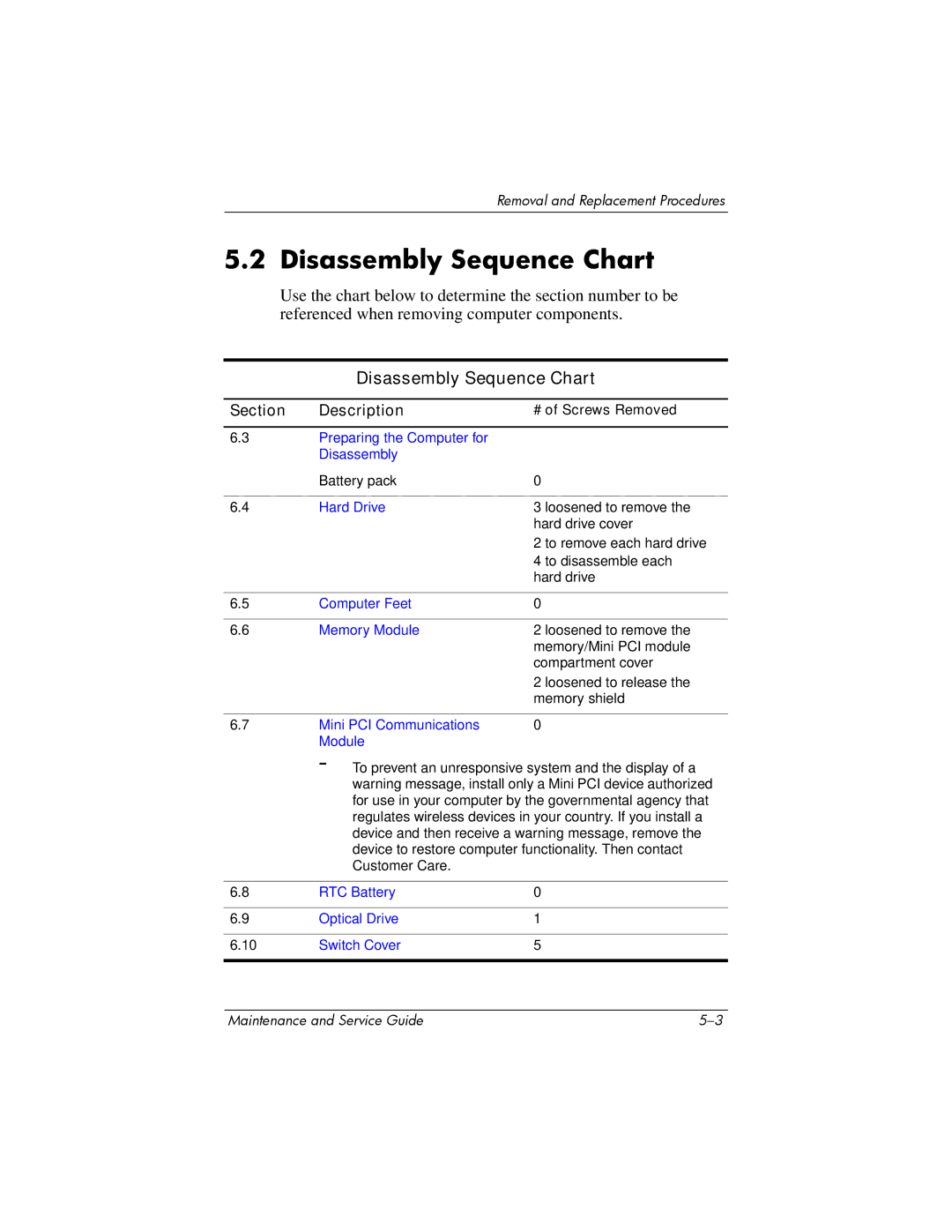
Use the chart below to determine the section number to be referenced when removing computer components.
Disassembly Sequence Chart
Section | Description | # of Screws Removed |
6.3Preparing the Computer for Disassembly
| Battery pack | 0 |
|
|
|
6.4 | Hard Drive | 3 loosened to remove the |
|
| hard drive cover |
|
| 2 to remove each hard drive |
|
| 4 to disassemble each |
|
| hard drive |
|
|
|
6.5 | Computer Feet | 0 |
|
|
|
6.6 | Memory Module | 2 loosened to remove the |
|
| memory/Mini PCI module |
|
| compartment cover |
|
| 2 loosened to release the |
|
| memory shield |
|
|
|
6.7 | Mini PCI Communications | 0 |
| Module |
|
| Å To prevent an unresponsive system and the display of a | |
| warning message, install only a Mini PCI device authorized | |
| for use in your computer by the governmental agency that | |
| regulates wireless devices in your country. If you install a | |
| device and then receive a warning message, remove the | |
| device to restore computer functionality. Then contact | |
| Customer Care. |
|
|
|
|
6.8 | RTC Battery | 0 |
|
|
|
6.9 | Optical Drive | 1 |
|
|
|
6.10 | Switch Cover | 5 |
|
|
|
Maintenance and Service Guide |