6.Remove the optical drive (see Optical drive on page 42).
7.Remove the hard drive (see Hard drive on page 44).
8.Remove the keyboard (see Keyboard on page 51).
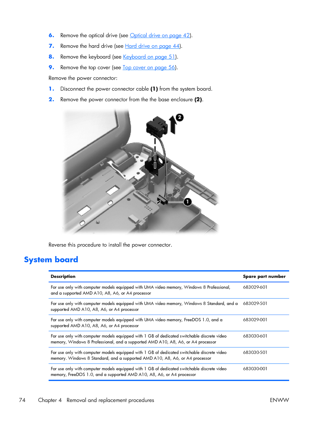
9.Remove the top cover (see Top cover on page 56). Remove the power connector:
1.Disconnect the power connector cable (1) from the system board.
2.Remove the power connector from the the base enclosure (2).
Reverse this procedure to install the power connector.
System board
Description | Spare part number |
|
|
For use only with computer models equipped with UMA video memory, Windows 8 Professional, | |
and a supported AMD A10, A8, A6, or A4 processor |
|
|
|
For use only with computer models equipped with UMA video memory, Windows 8 Standard, and a | |
supported AMD A10, A8, A6, or A4 processor |
|
|
|
For use only with computer models equipped with UMA video memory, FreeDOS 1.0, and a | |
supported AMD A10, A8, A6, or A4 processor |
|
|
|
For use only with computer models equipped with 1 GB of dedicated switchable discrete video | |
memory, Windows 8 Professional, and a supported AMD A10, A8, A6, or A4 processor |
|
|
|
For use only with computer models equipped with 1 GB of dedicated switchable discrete video | |
memory. Windows 8 Standard, and a supported AMD A10, A8, A6, or A4 processor |
|
|
|
For use only with computer models equipped with 1 GB of dedicated switchable discrete video | |
memory, FreeDOS 1.0, and a supported AMD A10, A8, A6, or A4 processor |
|
|
|
74 | Chapter 4 Removal and replacement procedures | ENWW |
