Electrical Tests
Test Electrode Resistance
1.Prepare the gun for service as instructed on page 41.
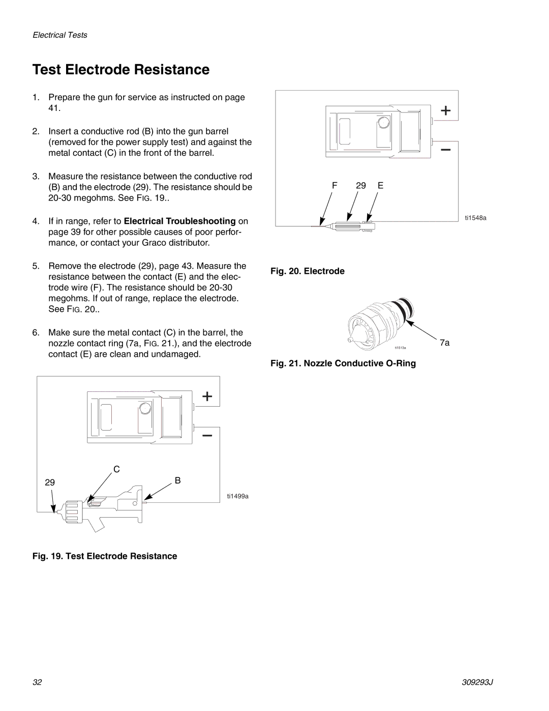
2.Insert a conductive rod (B) into the gun barrel (removed for the power supply test) and against the metal contact (C) in the front of the barrel.
3.Measure the resistance between the conductive rod
(B) and the electrode (29). The resistance should be
4.If in range, refer to Electrical Troubleshooting on page 39 for other possible causes of poor perfor- mance, or contact your Graco distributor.
5.Remove the electrode (29), page 43. Measure the resistance between the contact (E) and the elec- trode wire (F). The resistance should be
6.Make sure the metal contact (C) in the barrel, the nozzle contact ring (7a, FIG. 21.), and the electrode contact (E) are clean and undamaged.
C
29 | B |
ti1499a
F 29 E
ti1548a
Fig. 20. Electrode
7a
ti1513a
Fig. 21. Nozzle Conductive O-Ring
Fig. 19. Test Electrode Resistance
32 | 309293J |
