Installation
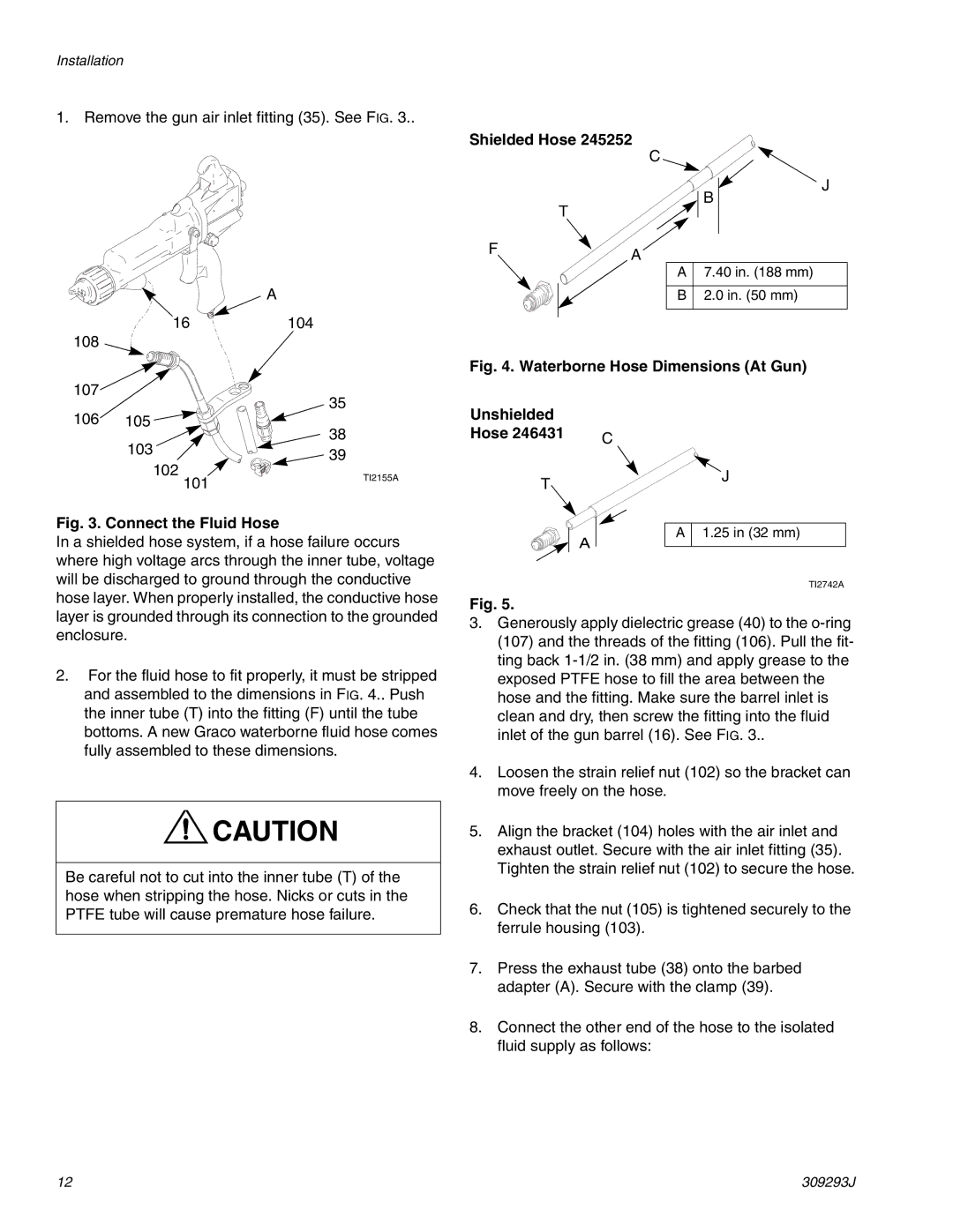
1. Remove the gun air inlet fitting (35). See FIG. 3..
A
16104
108
107![]()
Shielded Hose 245252
C
J
B
T
FA
A 7.40 in. (188 mm)
B 2.0 in. (50 mm)
Fig. 4. Waterborne Hose Dimensions (At Gun)
106 | 35 |
105 |
103 |
| 38 | |
| 39 | ||
102 |
| ||
101 | TI2155A | ||
| |||
|
|
Fig. 3. Connect the Fluid Hose
In a shielded hose system, if a hose failure occurs where high voltage arcs through the inner tube, voltage will be discharged to ground through the conductive hose layer. When properly installed, the conductive hose
Unshielded |
|
Hose 246431 | C |
| |
T |
|
| A |
J
A 1.25 in (32 mm)
TI2742A
layer is grounded through its connection to the grounded enclosure.
2.For the fluid hose to fit properly, it must be stripped and assembled to the dimensions in FIG. 4.. Push the inner tube (T) into the fitting (F) until the tube bottoms. A new Graco waterborne fluid hose comes fully assembled to these dimensions.
![]() CAUTION
CAUTION
Be careful not to cut into the inner tube (T) of the hose when stripping the hose. Nicks or cuts in the PTFE tube will cause premature hose failure.
Fig. 5.
3.Generously apply dielectric grease (40) to the
4.Loosen the strain relief nut (102) so the bracket can move freely on the hose.
5.Align the bracket (104) holes with the air inlet and exhaust outlet. Secure with the air inlet fitting (35). Tighten the strain relief nut (102) to secure the hose.
6.Check that the nut (105) is tightened securely to the ferrule housing (103).
7.Press the exhaust tube (38) onto the barbed adapter (A). Secure with the clamp (39).
8.Connect the other end of the hose to the isolated fluid supply as follows:
12 | 309293J |
