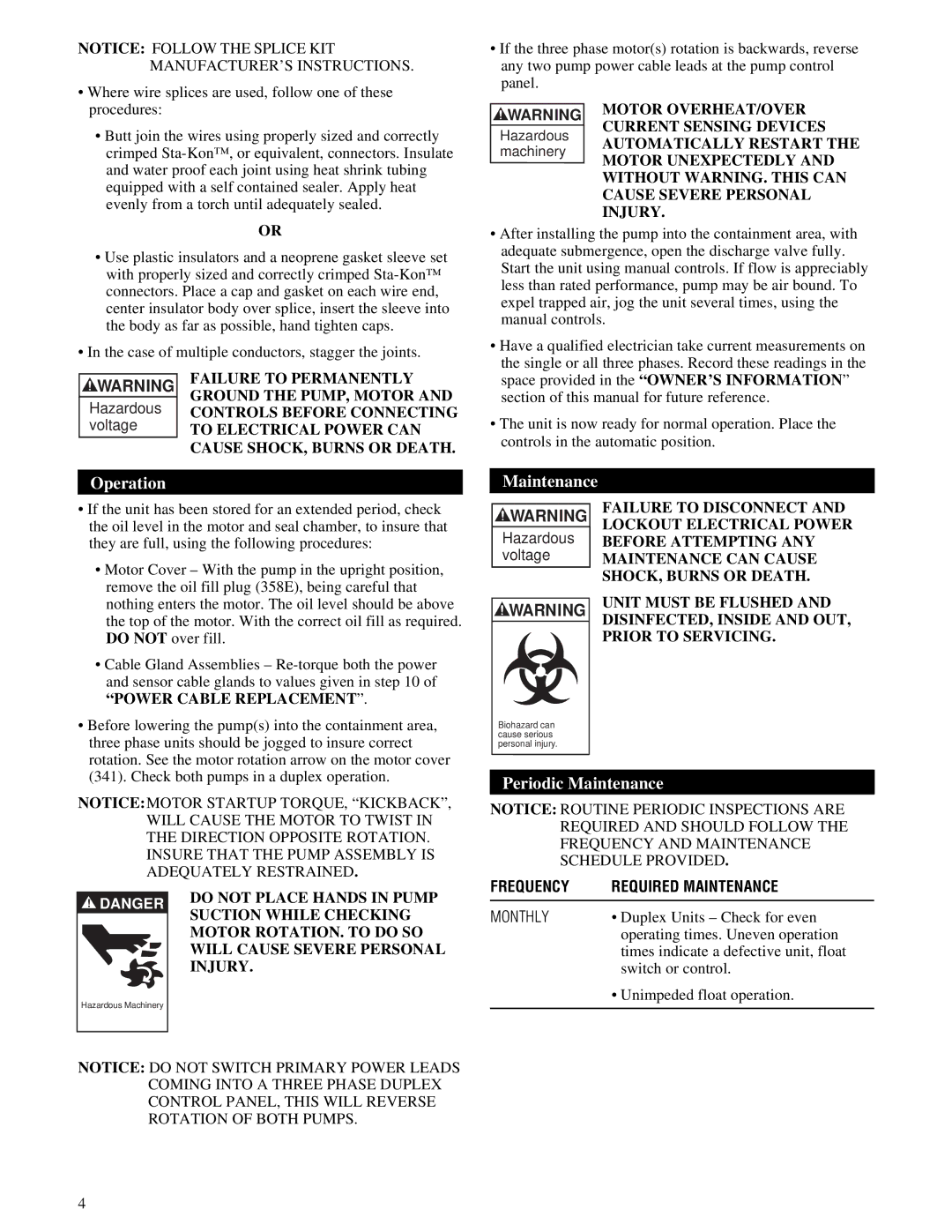
NOTICE: FOLLOW THE SPLICE KIT MANUFACTURER’S INSTRUCTIONS.
•Where wire splices are used, follow one of these procedures:
•Butt join the wires using properly sized and correctly crimped
OR
•Use plastic insulators and a neoprene gasket sleeve set with properly sized and correctly crimped
•In the case of multiple conductors, stagger the joints.
WARNING | FAILURE TO PERMANENTLY | |
GROUND THE PUMP, MOTOR AND | ||
Hazardous | ||
CONTROLS BEFORE CONNECTING | ||
voltage | TO ELECTRICAL POWER CAN | |
| CAUSE SHOCK, BURNS OR DEATH. |
•If the three phase motor(s) rotation is backwards, reverse any two pump power cable leads at the pump control panel.
WARNING | MOTOR OVERHEAT/OVER | |
CURRENT SENSING DEVICES | ||
Hazardous | ||
AUTOMATICALLY RESTART THE | ||
machinery | ||
MOTOR UNEXPECTEDLY AND | ||
| ||
| WITHOUT WARNING. THIS CAN |
CAUSE SEVERE PERSONAL
INJURY.
•After installing the pump into the containment area, with adequate submergence, open the discharge valve fully. Start the unit using manual controls. If flow is appreciably less than rated performance, pump may be air bound. To expel trapped air, jog the unit several times, using the manual controls.
•Have a qualified electrician take current measurements on the single or all three phases. Record these readings in the space provided in the “OWNER’S INFORMATION ” section of this manual for future reference.
•The unit is now ready for normal operation. Place the controls in the automatic position.
Operation
•If the unit has been stored for an extended period, check the oil level in the motor and seal chamber, to insure that they are full, using the following procedures:
•Motor Cover – With the pump in the upright position, remove the oil fill plug (358E), being careful that nothing enters the motor. The oil level should be above the top of the motor. With the correct oil fill as required. DO NOT over fill.
•Cable Gland Assemblies –
“POWER CABLE REPLACEMENT ”.
•Before lowering the pump(s) into the containment area, three phase units should be jogged to insure correct rotation. See the motor rotation arrow on the motor cover (341). Check both pumps in a duplex operation.
NOTICE: MOTOR STARTUP TORQUE, “KICKBACK”, WILL CAUSE THE MOTOR TO TWIST IN THE DIRECTION OPPOSITE ROTATION. INSURE THAT THE PUMP ASSEMBLY IS ADEQUATELY RESTRAINED.
Maintenance
WARNING | FAILURE TO DISCONNECT AND | |
LOCKOUT ELECTRICAL POWER | ||
Hazardous | ||
BEFORE ATTEMPTING ANY | ||
voltage | MAINTENANCE CAN CAUSE | |
| SHOCK, BURNS OR DEATH. | |
| UNIT MUST BE FLUSHED AND | |
WARNING | ||
DISINFECTED, INSIDE AND OUT, | ||
| ||
| PRIOR TO SERVICING. |
Biohazard can cause serious personal injury.
Periodic Maintenance
NOTICE: ROUTINE PERIODIC INSPECTIONS ARE REQUIRED AND SHOULD FOLLOW THE FREQUENCY AND MAINTENANCE SCHEDULE PROVIDED.
! DANGER |
Hazardous Machinery |
DO NOT PLACE HANDS IN PUMP SUCTION WHILE CHECKING MOTOR ROTATION. TO DO SO WILL CAUSE SEVERE PERSONAL INJURY.
FREQUENCY | REQUIRED MAINTENANCE |
MONTHLY | • Duplex Units – Check for even |
| operating times. Uneven operation |
| times indicate a defective unit, float |
| switch or control. |
| • Unimpeded float operation. |
|
|
NOTICE: DO NOT SWITCH PRIMARY POWER LEADS COMING INTO A THREE PHASE DUPLEX CONTROL PANEL, THIS WILL REVERSE ROTATION OF BOTH PUMPS.
4
