Hard Drive Installation Guidelines
■
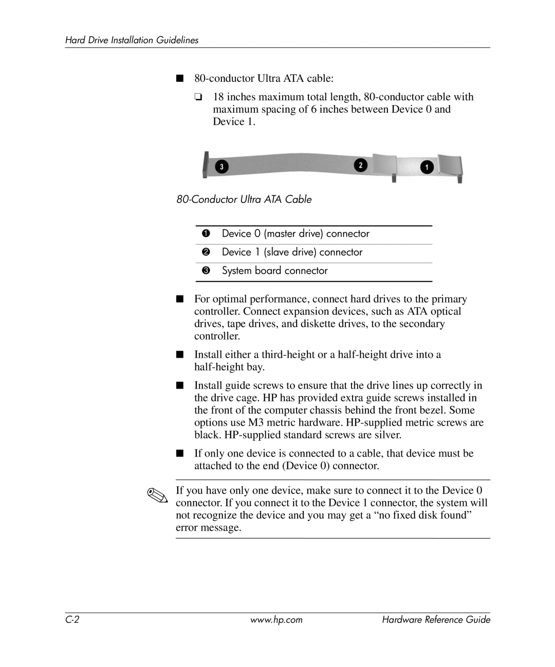
❏18 inches maximum total length,
80-Conductor Ultra ATA Cable
1Device 0 (master drive) connector
2Device 1 (slave drive) connector
3System board connector
■For optimal performance, connect hard drives to the primary controller. Connect expansion devices, such as ATA optical drives, tape drives, and diskette drives, to the secondary controller.
■Install either a
■Install guide screws to ensure that the drive lines up correctly in the drive cage. HP has provided extra guide screws installed in the front of the computer chassis behind the front bezel. Some options use M3 metric hardware.
■If only one device is connected to a cable, that device must be attached to the end (Device 0) connector.
✎If you have only one device, make sure to connect it to the Device 0 connector. If you connect it to the Device 1 connector, the system will not recognize the device and you may get a “no fixed disk found” error message.
www.hp.com | Hardware Reference Guide |
