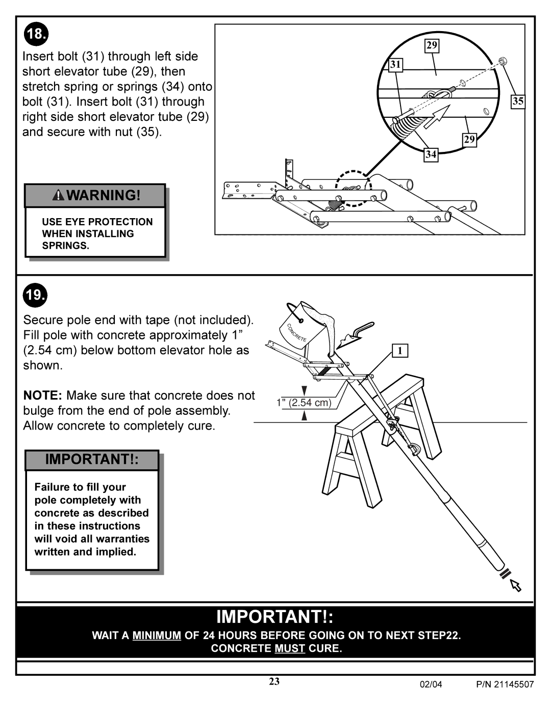
Contents
N53 W24700 South Corporate Circle Sussex, WI 53089 U.S.A
Customer Service Center
Toll-Free Customer Service Number for U.S For Canada
Inground System Owners Manual
BEFORE YOU START
Do not slide, climb, shake or play on pole
Owner must ensure that all players know and follow
these rules for safe operation of the system
P/N 21145507 02/04
SAFETY INSTRUCTIONS
HEIGHT ADJUSTMENT
NOTICE TO ASSEMBLERS
Remove all contents from boxes
PARTS LIST - See Hardware Identifier
HARDWARE IDENTIFIER NUTS & WASHERS
HARDWARE IDENTIFIER BOLTS & SCREWS
Item #23 Item #8 Item #27 1 Item #16 Item #12 Item #24 Item #31
Item #36
a Phillips-Head Screwdriver
SECTION A ASSEMBLE THE POLE
2 1/2”, 2 9/16” AND 2 3/4” Wrenches AND/OR
2 Socket Wrenches and Sockets 1/2” 9/16” AND
Tape Not Supplied
MIDDLE
BOTTOM
CONTACT UTILITIES BEFORE DIGGING
SIDE VIEW
FIG. A
FIG. B FIG. C
FLANGE
Note A
SIDE VIEW
Note A
Note B
7. Install ground sleeve cap 5 onto
10. Attach spacers 10, 11 to pole mount bracket 7 with bolts 12, washers 13, and nuts 14 as shown. IMPORTANT! Tighten until washers 13 no longer move
20 shown in illustration
SIDE ACCESS
Indicator labels should be applied as close to holes as possible as
to prevent labels from being damaged during height adjustment
2 Socket Wrenches and Sockets
SECTION B ASSEMBLE THE BACKBOARD TO ELEVATOR TUBES
ASSEMBLY WILL VARY DUE TO BACKBOARD STYLE
2 1/2, 2 9/16” AND 2 3/4” Wrenches AND/OR
1B. Assemble elevator tubes 30 as shown. Tighten completely
02/04
Use the following assembly instructions if you have a
48 molded plastic backboard Fan
2B. Assemble elevator tubes 30 as shown. Tighten completely
3A. Assemble backboard brackets to board as shown Refer To
a 44” steel-framed acrylic backboard
Use the following assembly instructions if you have a
Instructions Included With Backboard Hardware For Board Assembly
Included With Rim
Assembly
Refer To
Instructions
Install spacers 25, and springs 39 onto backboard
48” molded plastic-framed acrylic backboard
Use the following assembly instructions if you have a
3/4”
SECTION C ATTACH THE BACKBOARD/ELEVATOR TO POLE SYSTEM
BACKBOARD WILL VARY
2 3/4” Wrenches AND/OR 2 Socket Wrenches and Sockets
17. Install handle assembly to long
CONCRETE MUST CURE
USE EYE PROTECTION WHEN INSTALLING SPRINGS
WAIT A MINIMUM OF 24 HOURS BEFORE GOING ON TO NEXT STEP22
Page
02/04
NET INSTALLATION
Insert net into bottom of clip as shown
IMPORTANT! The elevator holes MUST be parallel with playing surface
Note A
NOTE A Do not use washers here on spring return style rim
Note A
C. Replace pin 26 full length to lock system at desired height
B C A
25. A. While holding handle, remove pin
B. Move elevator up or down to desired height