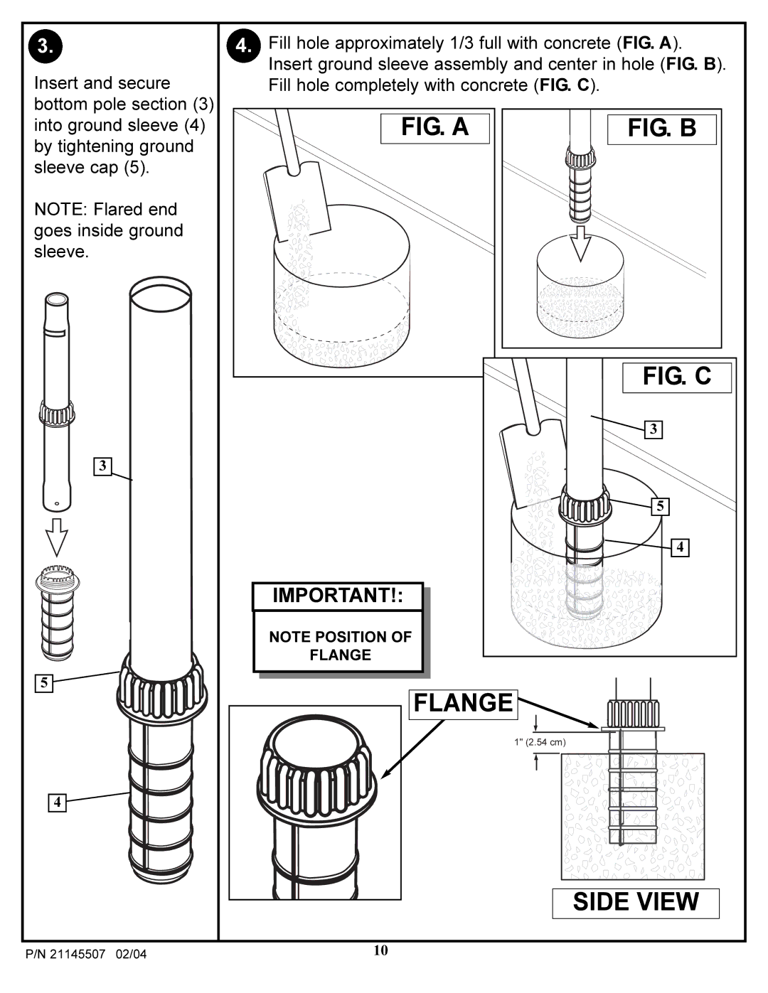
3.
Insert and secure bottom pole section (3)
4.Fill hole approximately 1/3 full with concrete (FIG. A). Insert ground sleeve assembly and center in hole (FIG. B). Fill hole completely with concrete (FIG. C).
into ground sleeve (4) by tightening ground sleeve cap (5).
NOTE: Flared end goes inside ground sleeve.
3
FIG. A
IMPORTANT!:
NOTE POSITION OF
FLANGE
FIG. B
FIG. C
![]() 3
3
5
![]()
![]()
![]()
![]()
![]() 4
4
5
4
FLANGE
1" (2.54 cm)
SIDE VIEW
P/N 21145507 02/04 | 10 |