www..reelsche93x Man
1.Place the control head into the gimbal bracket. Make sure that the straight side of the gimbal arm is against the back side of the control head.
2.Place a 1" (25 mm) diameter black washer on the gimbal knob and then thread the knob and washer into the housing. Tighten the gimbal knob to secure the 900 Series™ control head to the mount. Repeat step 2 for the other side.
You can now place the control head in various locations to decide which is best for mounting. Rotating the mounting bracket to the top of the control head will allow for overhead mounting. The chosen mounting area should allow for sufficient room so the control head can pivot through the full tilt range and allow for easy removal and installation.
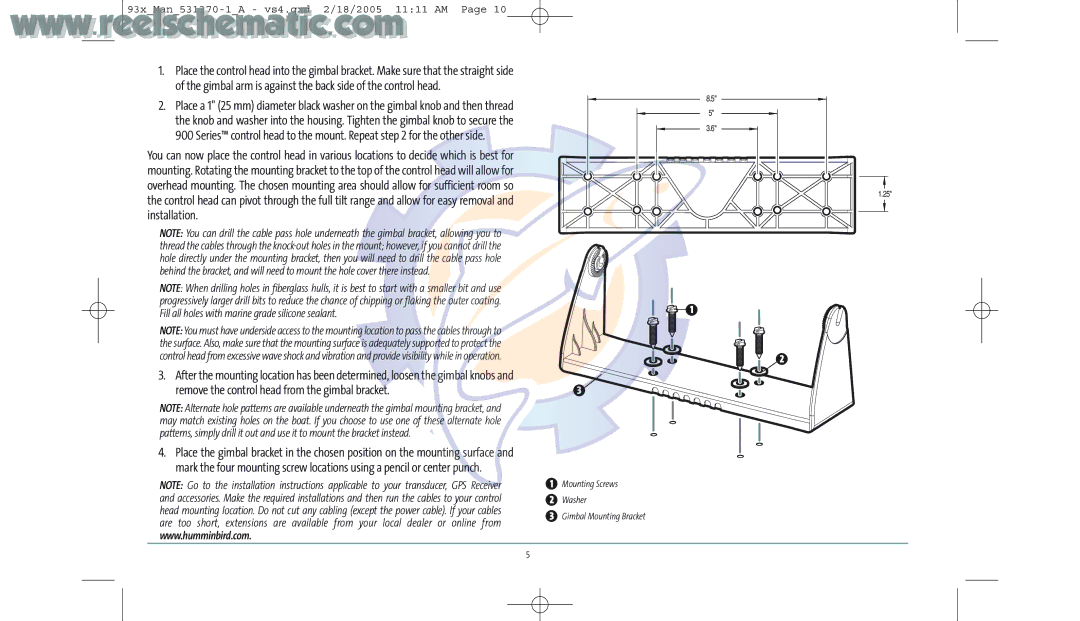
NOTE: You can drill the cable pass hole underneath the gimbal bracket, allowing you to thread the cables through the
NOTE: When drilling holes in fiberglass hulls, it is best to start with a smaller bit and use progressively larger drill bits to reduce the chance of chipping or flaking the outer coating. Fill all holes with marine grade silicone sealant.
NOTE: You must have underside access to the mounting location to pass the cables through to the surface. Also, make sure that the mounting surface is adequately supported to protect the control head from excessive wave shock and vibration and provide visibility while in operation.
3.After the mounting location has been determined, loosen the gimbal knobs and remove the control head from the gimbal bracket.
NOTE: Alternate hole patterns are available underneath the gimbal mounting bracket, and may match existing holes on the boat. If you choose to use one of these alternate hole patterns, simply drill it out and use it to mount the bracket instead.
4.Place the gimbal bracket in the chosen position on the mounting surface and mark the four mounting screw locations using a pencil or center punch.
NOTE: Go to the installation instructions applicable to your transducer, GPS Receiver and accessories. Make the required installations and then run the cables to your control head mounting location. Do not cut any cabling (except the power cable). If your cables are too short, extensions are available from your local dealer or online from www.humminbird.com.
8.5" |
5" |
3.6" |
1.25"
1
2
3![]()
1Mounting Screws
2Washer
3Gimbal Mounting Bracket
5
