9. TROUBLE SHOOTING
3.Connect the charging station to the power supply. Switch the connections between the guide wire and the boundary wire in the charging station.
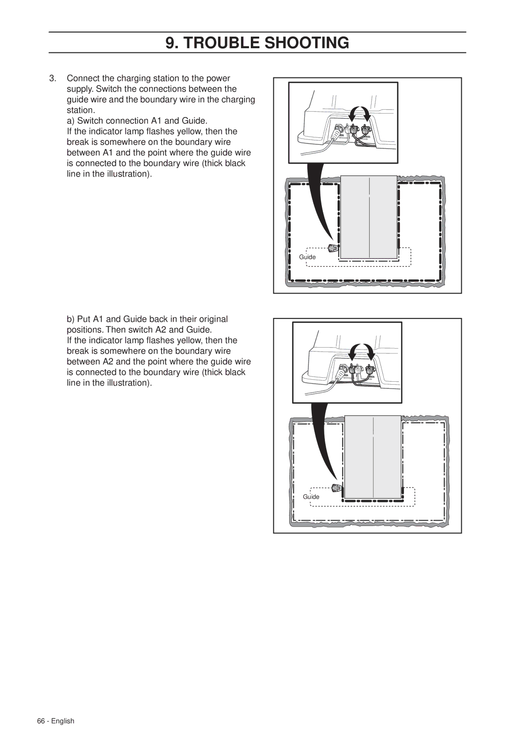
a) Switch connection A1 and Guide.
If the indicator lamp flashes yellow, then the break is somewhere on the boundary wire between A1 and the point where the guide wire is connected to the boundary wire (thick black line in the illustration).
Guide |
b)Put A1 and Guide back in their original positions. Then switch A2 and Guide.
If the indicator lamp flashes yellow, then the break is somewhere on the boundary wire between A2 and the point where the guide wire is connected to the boundary wire (thick black line in the illustration).
Guide |
66 - English