| |
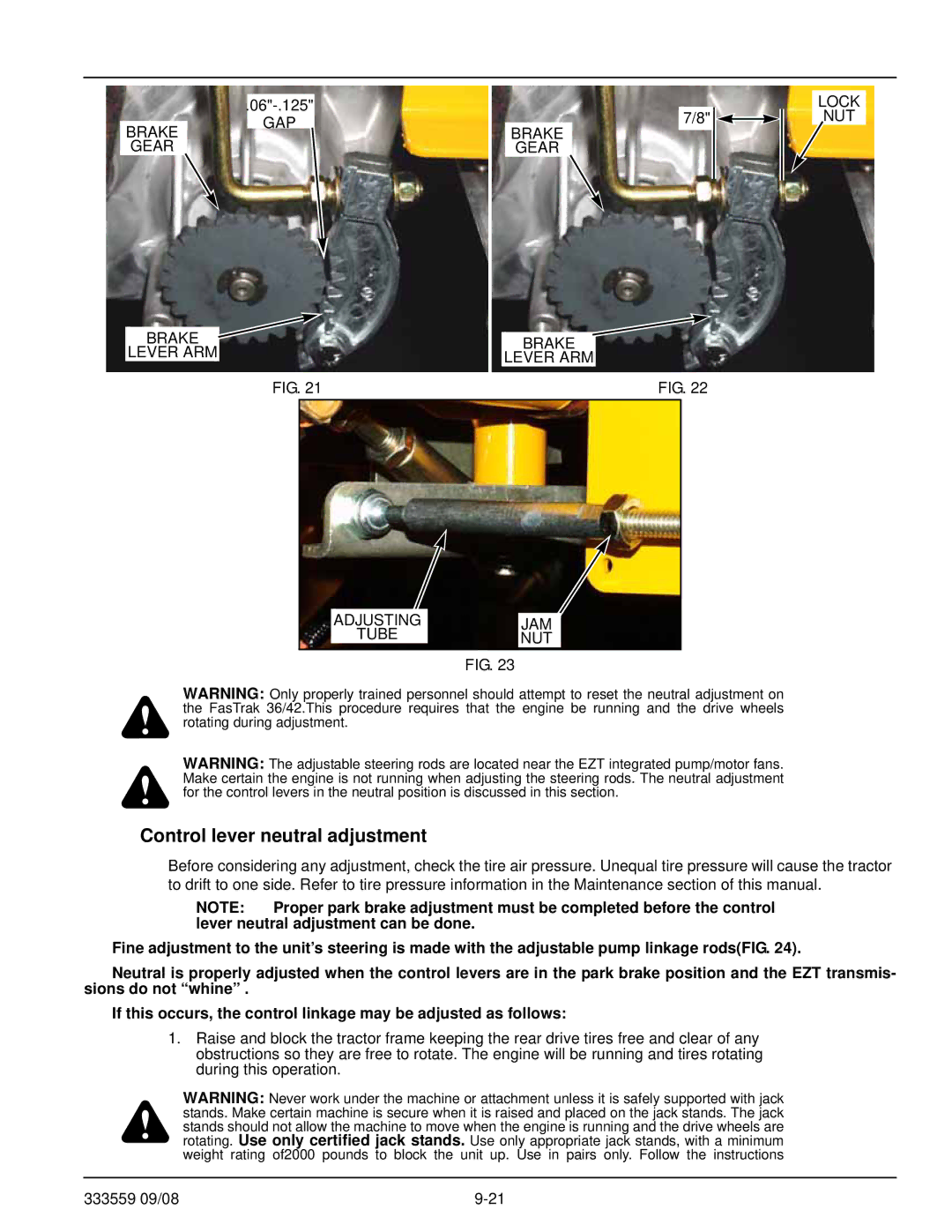
BRAKE | GAP |
| |
GEAR |
|
BRAKE ![]() LEVER ARM
LEVER ARM
FIG. 21
7/8" | LOCK |
NUT | |
BRAKE |
|
GEAR |
|
BRAKE
LEVER ARM
FIG. 22
ADJUSTING
TUBE
JAM |
NUT |
FIG. 23
WARNING: Only properly trained personnel should attempt to reset the neutral adjustment on the FasTrak 36/42.This procedure requires that the engine be running and the drive wheels rotating during adjustment.
WARNING: The adjustable steering rods are located near the EZT integrated pump/motor fans. Make certain the engine is not running when adjusting the steering rods. The neutral adjustment for the control levers in the neutral position is discussed in this section.
Control lever neutral adjustment
Before considering any adjustment, check the tire air pressure. Unequal tire pressure will cause the tractor to drift to one side. Refer to tire pressure information in the Maintenance section of this manual.
NOTE: Proper park brake adjustment must be completed before the control lever neutral adjustment can be done.
Fine adjustment to the unit’s steering is made with the adjustable pump linkage rods(FIG. 24).
Neutral is properly adjusted when the control levers are in the park brake position and the EZT transmis- sions do not “whine” .
If this occurs, the control linkage may be adjusted as follows:
1.Raise and block the tractor frame keeping the rear drive tires free and clear of any obstructions so they are free to rotate. The engine will be running and tires rotating during this operation.
WARNING: Never work under the machine or attachment unless it is safely supported with jack stands. Make certain machine is secure when it is raised and placed on the jack stands. The jack stands should not allow the machine to move when the engine is running and the drive wheels are rotating. Use only certified jack stands. Use only appropriate jack stands, with a minimum weight rating of2000 pounds to block the unit up. Use in pairs only. Follow the instructions
333559 09/08 |
