NOTE: The front brake link is not adjustable. Fig.
2.Raise and block the tractor up so the drive wheels are off of the floor.
3.Open the hydraulic pump’s bypass valve (Fig.
4.Rotate the tire. The tire should rotate. Remember hydraulic oil resistance will prevent the tire from rotating freely even with the bypass valves open. There should be no resistance from the brakes at this point.
5.Move the control lever to where it is just inside (1/8”) the park brake slot. Fig.
NOTE: When the control lever is against the outside edge of the the slot, the brakes should not be engaged. Fig.
6.Rotate the tire. If the brake is adjusted properly the tire will still rotate but friction will start to become noticeable here. However, if no brake resistance is noticed, the brake needs adjusted as follows:
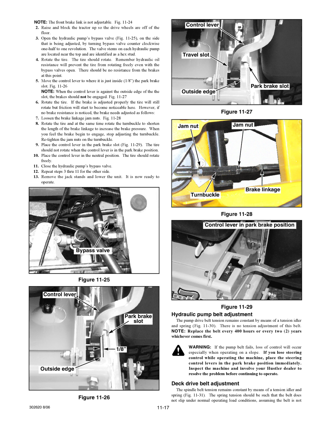
7.Loosen the brake linkage jam nuts. Fig. 11-28
8.Rotate the tire and at the same time rotate the turnbuckle to shorten the length of the brake linkage to increase the brake pressure. When you feel the brake begin to engage, stop adjusting the turnbuckle.
9.Place the control lever in the park brake slot (Fig.
10.Place the control lever in the neutral position. The tire should rotate freely.
11.Close the hydraulic pump’s bypass valve.
12.Repeat steps 3 thru 11 for the other side.
13.Remove the jack stands and lower the unit. It is now ready to operate.
Bypass valve
Figure
Control lever
Park brake
slot
![]() 1/8”
1/8”
Outside edge![]()
Figure
Control lever
Travel slot![]()
Park brake slot
Outside edge
Figure
Jam nut | Jam nut |
Brake linkage
Turnbuckle
Figure
Control lever in park brake position
Figure
Hydraulic pump belt adjustment
The pump drive belt tension remains constant by means of a tension idler and spring (Fig.
NOTE: Replace the belt every 400 hours or every two (2) years whichever comes first.
WARNING: If the pump belt fails, loss of control will occur especially when operating on a slope. If you lose steering control while operating the machine, place the steering control levers in the park brake position immediately. Inspect the machine and involve your Hustler dealer to resolve the problem before continuing to operate.
Deck drive belt adjustment
The spindle belt tension remains constant by means of a tension idler and spring (Fig.
302620 8/06 |