Manuals
/
Hustler Turf
/
Lawn and Garden
/
Lawn Mower
Hustler Turf
Super Mini Z
manual
Battery Installation
Models:
Super Mini Z
1
16
102
102
Download
102 pages
39.47 Kb
13
14
15
16
17
18
19
20
Install
Error codes
Electrical Schematic-Kohler
Deck Lift Indicator
Wiring Clamp
Maintenance
Footrest Assembly
Battery Clamp Strap
Adjustments
Engine RPM setting
Page 16
Image 16
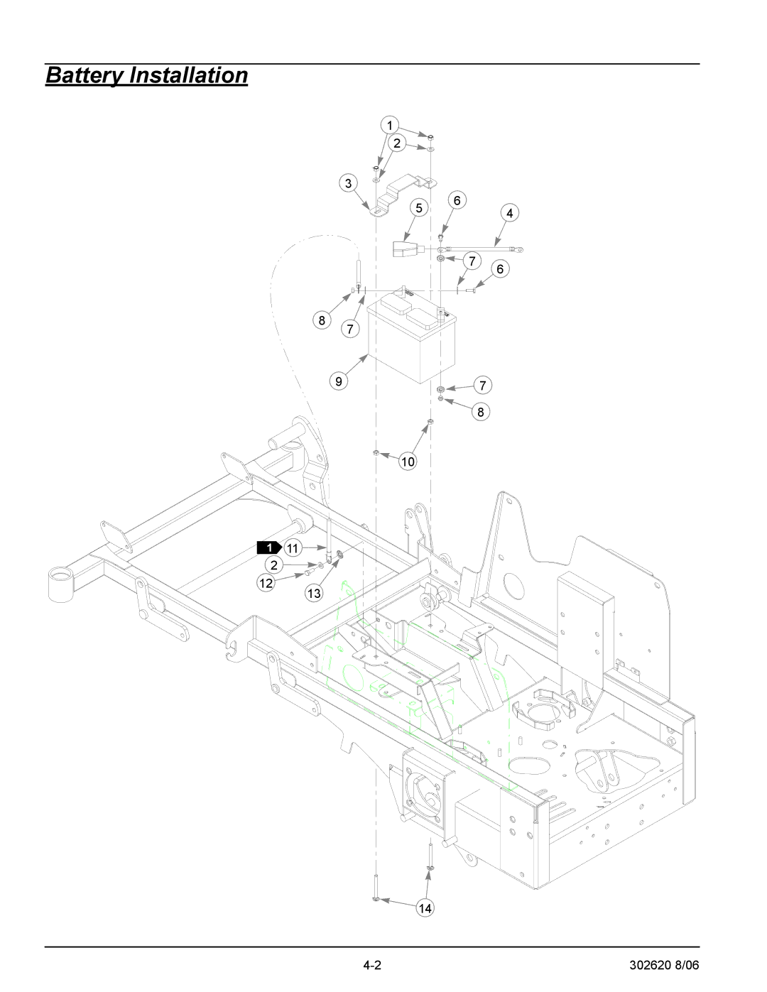
Battery Installation
1
2
3
5
6
4
7
6
8
7
9
10
1
11
2
12
13
14
7
8
4-2
302620 8/06
Page 15
Page 17
Page 16
Image 16
Page 15
Page 17
Contents
Hustler Super Mini Z Parts Manual
This spark ignition system complies with Canadian ICES-002
Table of Contents
Contents
General Information
Service Literature
Frequently Ordered Parts
Hardware Description Codes & Abbreviations
Contents
Mini Z Frame
Rivet-nut Installation
Thread Nutsert
Footrest Assembly
Mini Z Floor Plate
Upper Step Tread
Lower Step Tread
302620 8/06
Contents
Hydraulic System Installation
MINI-Z Case Drain Hose Assembly
Hose ASSEMBLY, Pump to Cooler SMZ
Hose ASSEMBLY, Reservoir to Filter SMZ
Hose ASSEMBLY, Filter to Pump SMZ
Seal Kit for hydraulic pump 788133 BDP16 Overhaul Seal Kit
Contents
Battery Installation
Battery Clamp Strap
Positive Battery Cable
RED Battery Cable Boot
Battery
Deck Lift Assembly
Height Adjustment Stop
Deck Lift Indicator
Stop Handle
Deck Lift Spring
Steering and Brake Assembly
Brake ROD Assembly
Pump ROD Adjuster Assembly
Push Button Switch
Brake Linkage Assemblyy
302620 8/06
This page intentionally left blank
Pump Belt and Pulley Installation
Wiring Clamp
Super Z Single Pulley
Clutch Pigtail Harness Diode
Warner Z Clutch
302620 8/06
Contents
Kawasaki Engine Installation
Donaldson AIR Cleaner CAP
AIR Filter Indicator
AIR Cleaner
Battery Cable
Main AIR Filter Element Vacuator Valve
This page intentionally left blank
Honda Engine Installation
Centrifical AIR Cleaner CAP
Honda Aircleaner Hose Clamp
Honda 24 HP Engine Used on
Honda OIL Drain Valve
Main AIR Filter Element Vacuator Valve
This page intentionally left blank
Kohler Engine Installation
Wire Harness
Kohler CV740 Engine 27 HP
Kohler Muffler
NT .375-16 Hxflk Znyc
302620 8/06
This page intentionally left blank
Fuel System Installation
Fuel Tank CAP
Right Side Fuel Tank
Left Side Fuel Tank
FITTING, Fuel Tank
Instrument Panel Installation/Assembly
PTO Switch
RED Indicator Light
KEY Switch
Delay Module
Electrical Schematic Kawasaki Engines
Electrical Schematic Kawasaki Engines
Electrical Schematic Honda Engines
Electrical Schematic Honda Engines
Electrical Schematic-Kohler
Electrical Schematic-Kohler
302620 8/06
Contents
Front Wheel Assembly
Optional SEMI-PNEUMATIC TIRE/WHEEL Assembly
Bearing Disc
Bearing W/O Collar
Spacer
Front Wheel Breakdown
Wheel Bearing
Wheel
Tire Valve
Drive Wheel Assembly/Installation
WHEEL/TIRE Assembly 23 X
Wheel NUT QTY PER Wheel
Wheel LUG Stud QTY PER Wheel
Anti Rollover Wheel Bracket
Anti-Rollover Wheel Assembly
ANTI-SCALP Wheel
Contents
Deck Assembly
ANTI-SCALP Wheel Assembly
MINI-Z Deck
Discharge Chute
Discharge Chute Mount Bracket
Deck Pulley Assembly
Blade Spindle Assembly
Deck Belt
Deck Idler Uhmw Clamp
Deck Idler Uhmw Riser
Used on mower with serial number prior to
Blade Spindle Assembly Breakdown
302620 8/06
Contents
Deck Installation
Tractor Assembly Deck
Deck Belt Routing and Tensioning
302620 8/06
Contents
Tractor Decals
Service Decal
Fuel Indicator Decal
Battery Decal
Instrument Panel Decal
Deck Decals
Deck 44 ID Decal
302620 8/06
302620 8/06 10-1
Seat Installation
SMALL/SHORT Wire TIE
Seat Switch
Armrest Stop Assembly
Spring Plunger Latch
10-4 302620 8/06
Maintenance & Adjustments Safety Precautions
11-2
Safety Precautions
Safe Maintenance & Adjustment Practices
Using a ramp
Safety and Instruction Decals
11-6
Viewed from bottom of tractor
11-7
Introduction
Torque values
Hour meter
Lubrication
Battery Electric clutch
Access to engine and hydraulic pumps
Electrical system
Burnishing the electric clutch
Cooling fan Heat Engine
Fuel system
Fuel tank
Engine oil and filter
Engine oil filler tube
Pre-cleaner Canister
Engine oil Engine oil filter Drain plug
General engine maintenance
Reset Button Indicator
Belt replacement
Mower blade maintenance
Mower blade removal
Adjustments
Steering linkage
Park brake adjustment
11-16
Deck drive belt adjustment
Loosen the brake linkage jam nuts. Fig
Deck leveling and height adjustment
Engine RPM setting
Spring Tension Idler Pump drive Belt Tension idler Chain
Foot Nuts
Nut Chains Bolt Jam nut Hardware Adjuster
Deck lift Assist springs Lift block Deck lift rod
11-20
Index
Numerical Index
Part
Part
Top
Page
Image
Contents