3301690 CPU Card
Two gigabit connections can be made between the Ethernet connectors and a Local Area Network (LAN) through a network hub. An
| PIN |
|
| DESCRIPTION |
|
| PIN |
|
| DESCRIPTION |
|
| 1 |
|
| TXD+ |
| 8 |
|
| GND |
| |
|
|
|
|
|
|
|
|
|
|
| |
| 2 |
|
| TXD- |
| 9 |
|
| GRN+ |
| |
| 3 |
|
| RXD+ |
| 10 |
|
| GRN- |
| |
| 4 |
|
| CT_TXD |
| 11 |
|
| YEL- |
| |
|
|
|
|
|
|
|
|
|
|
| |
| 5 |
|
| CT_RXD |
| 12 |
|
| YEL+ |
| |
|
|
|
|
|
|
|
|
|
|
| |
| 6 |
|
| RXD- |
| 13 |
|
| S GND |
| |
|
|
|
|
|
|
|
|
|
|
| |
| 7 |
|
| N/C |
| 14 |
|
| S GND |
| |
Table 3-19: RJ-45 Ethernet Connector Pinouts
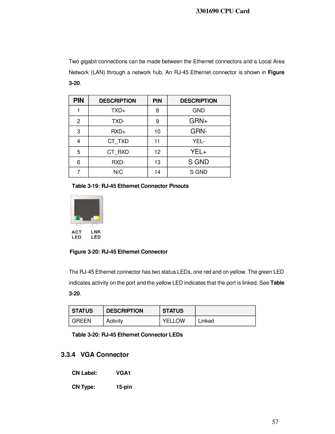
Figure 3-20: RJ-45 Ethernet Connector
The

 STATUS
GREEN
| DESCRIPTION |
| STATUS |
| Activity | YELLOW | |
|
|
|
|
Linked
Table
3.3.4 VGA Connector
CN Label: | VGA1 |
CN Type: |
57