3301690 CPU Card
CN Location: See Figure 3-18 (labeled number 7)
The standard
PIN
DESCRIPTION
PIN
DESCRIPTION
1
Red
9
No Connect
2
Green
10
Ground
3
Blue
11
No Connect
4
No Connect
12
DDC DAT
5
Ground
13
Horizontal Synchronization
6
Ground
14
Vertical Synchronization
7
Ground
15
DDC Clock
8
Ground
Table 3-21: VGA Connector Pinouts
3.4Onboard Jumpers
NOTE:
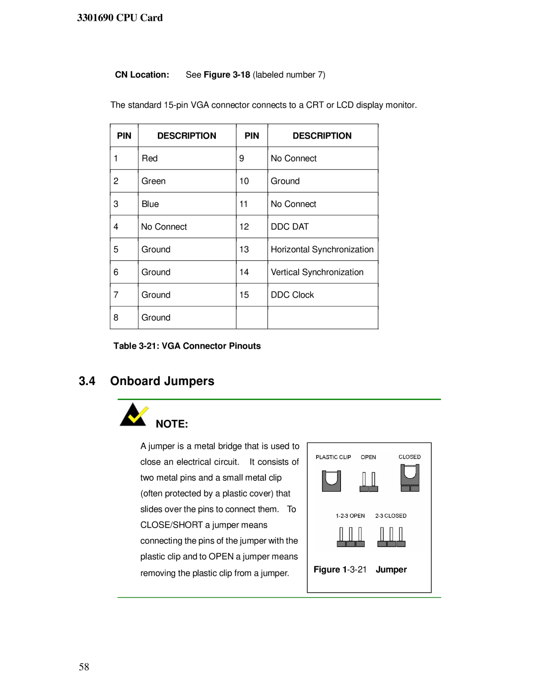
A jumper is a metal bridge that is used to close an electrical circuit. It consists of two metal pins and a small metal clip (often protected by a plastic cover) that slides over the pins to connect them. To CLOSE/SHORT a jumper means connecting the pins of the jumper with the plastic clip and to OPEN a jumper means removing the plastic clip from a jumper.
Figure 1-3-21 Jumper
58
