The STB NIB 1010 Basic NIM Module
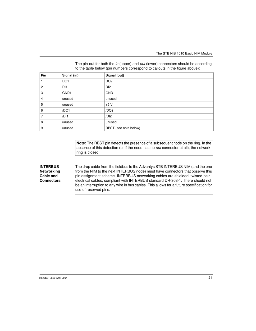
The
Pin | Signal (in) | Signal (out) |
|
|
|
1 | DO1 | DO2 |
|
|
|
2 | DI1 | DI2 |
|
|
|
3 | GND1 | GND |
|
|
|
4 | unused | unused |
|
|
|
5 | unused | +5 V |
|
|
|
6 | /DO1 | /DO2 |
|
|
|
7 | /DI1 | /DI2 |
|
|
|
8 | unused | unused |
|
|
|
9 | unused | RBST (see note below) |
|
|
|
| Note: The RBST pin detects the presence of a subsequent node on the ring. In the |
| absence of this detection (or if the node has no out connector at all), the network |
| ring is closed. |
INTERBUS |
|
| |
The drop cable from the fieldbus to the Advantys STB INTERBUS NIM (and the one | |
Networking | from the NIM to the next INTERBUS node) must have connectors that observe this |
Cable and | pin assignment scheme. INTERBUS networking cables are shielded, |
Connectors | electrical cables, compliant with INTERBUS standard |
| be an interruption to any wire in bus cables. This allows for a future specification for |
| use of reserved pins. |
|
|
890USE19600 April 2004 | 21 |
