The STB NIB 1010 Basic NIM Module
External Features of the STB NIB 1010 NIM
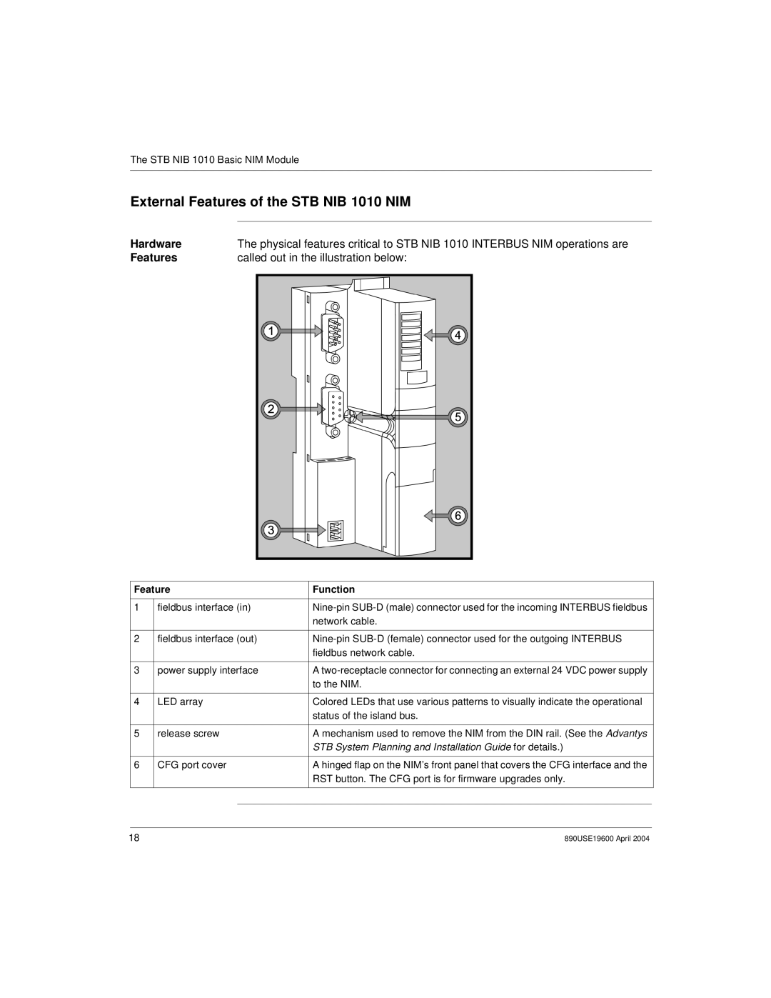
Hardware | The physical features critical to STB NIB 1010 INTERBUS NIM operations are |
Features | called out in the illustration below: |
Feature | Function |
| ||
|
|
|
| |
1 | fieldbus interface (in) |
| ||
|
|
| network cable. |
|
|
|
|
| |
2 | fieldbus interface (out) |
| ||
|
|
| fieldbus network cable. |
|
|
|
|
| |
3 | power supply interface | A |
| |
|
|
| to the NIM. |
|
|
|
|
| |
4 | LED array | Colored LEDs that use various patterns to visually indicate the operational |
| |
|
|
| status of the island bus. |
|
|
|
|
| |
5 | release screw | A mechanism used to remove the NIM from the DIN rail. (See the Advantys |
| |
|
|
| STB System Planning and Installation Guide for details.) |
|
|
|
|
| |
6 | CFG port cover | A hinged flap on the NIM’s front panel that covers the CFG interface and the |
| |
|
|
| RST button. The CFG port is for firmware upgrades only. |
|
|
|
|
|
|
|
|
|
|
|
|
|
|
|
|
18 | 890USE19600 April 2004 |