IBM
Page
IBM
First Edition July
Important Safety Information
About this manual
Iv Hardware Maintenance Manual
Contents
Additional Service Information
Acpi Bios
Set Power-On Self-Test to Enhanced
General Checkout
Did YOU Receive the Correct RESPONSE?
Features
General Information
Expansion
Specifications
Physical specification small desktop model
Physical specification desktop model
Physical specifications microtower model
Hardware Maintenance Manual
Diagnostics
Setup Utility program
Product Recovery Program menu
IBM Backup and Restore
Diagnostics
Diagnostics program download
Navigating through the diagnostics programs
Running diagnostics tests
Module test menu/hardware configuration report
Memory Diagnostic tests
Alert-On LAN test
Asset ID test
Test results
Hard file Smart test
Quick and Full erase hard drive
Asset Eeprom backup
Iomega Zip drive test
Viewing the test log
When to use the Low-Level Format program
Preparing the hard disk drive for use
Hardware Maintenance Manual
Installing Options
Locating the connectors on the front of your computer
Front USB connector
Installing Options
Locating the connectors on the rear of your computer
Installing Options
Hardware Maintenance Manual
Connector Description
Home PNA network adapter
Removing the cover small desktop model
Locating components small desktop model
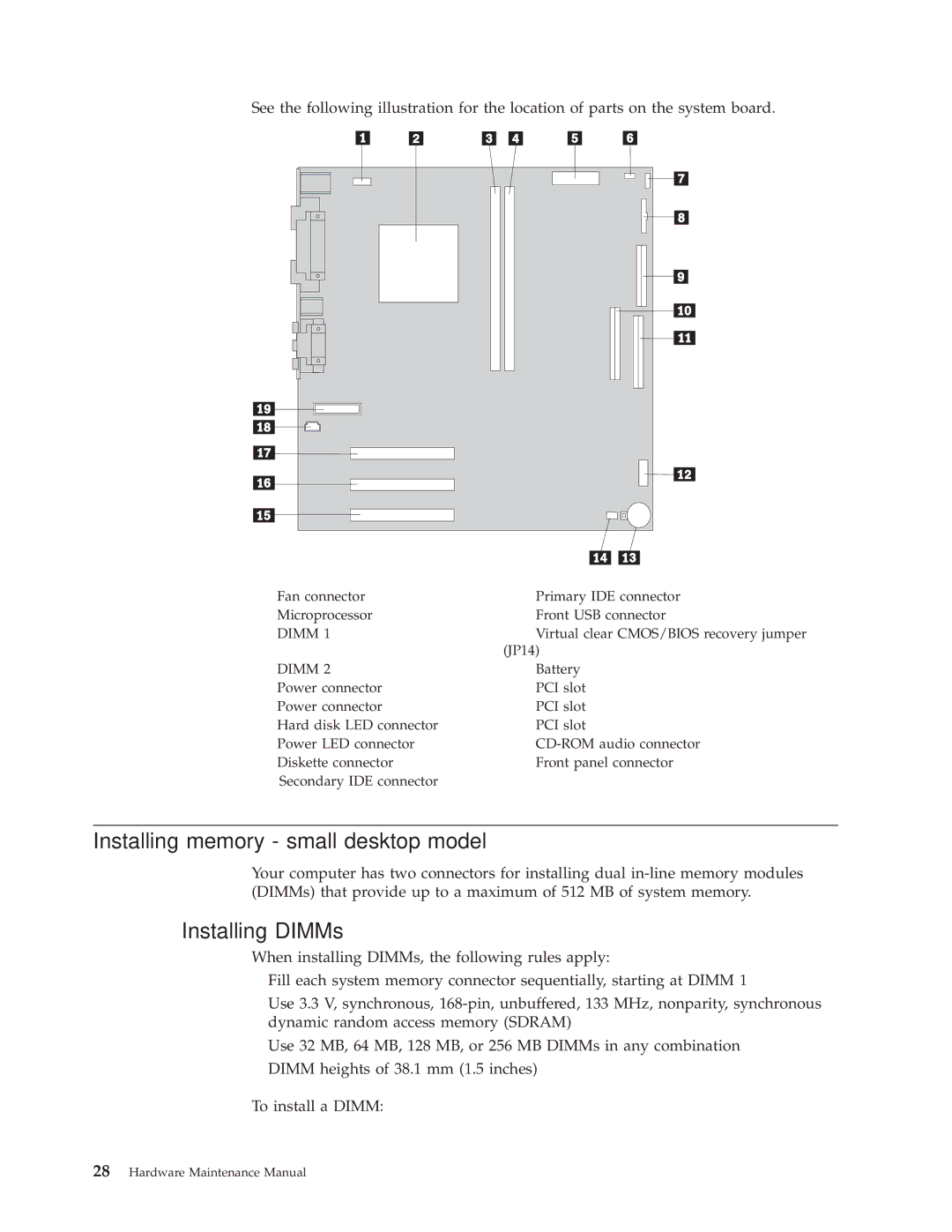
Identifying parts on the system board small desktop model
Dimm
Installing memory small desktop model
Installing DIMMs
Installing adapters small desktop model
What to do next
Installing internal drives small desktop model
Drive specifications
Installing a drive
What to do next
Installing a Rope Clip small desktop model
Removing the cover desktop model
Locating components desktop model
Identifying parts on the system board desktop model
Installing memory desktop model
Installing adapters desktop model
Installing internal drives desktop model
Drive specifications
Installing a drive
To connect the first IDE CD drive or DVD drive
Installing a Rope Clip desktop model
To connect an additional IDE CD drive or DVD drive
Replacing the cover and connecting the cables desktop model
Removing the cover microtower model
Installing Options
Moving the power supply microtower model
Locating components microtower model
Installing Options
Identifying parts on the system board microtower model
Installing memory microtower model
Installing adapters microtower model
Installing internal drives microtower model
Drive specifications
Installing a drive
To connect the first IDE CD drive or DVD drive
Installing a Rope Clip microtower model
To work with another option, go to the appropriate section
Installing Options
Hardware Maintenance Manual
FRU Replacements
Identifying parts on the system board
Replacing a System Board Small Desktop Model
Replacing a processor Small Desktop Model
Power supply removal Small Desktop Model
Replacing a System Board Desktop Model
Replacing a processor Desktop Model
Power supply removal Desktop Model
Replacing a system board Microtower Model
Power supply removal Microtower Model
Replacing a processor Microtower Model
FRU Replacements
Hardware Maintenance Manual
Symptom-to-FRU Index
Sdram memory errors
Hard disk drive boot error
Power Supply Errors
Check/Verify FRU/Action
Diagnostic error codes
Symptom-to-FRU Index
Hardware Maintenance Manual
Symptom-to-FRU Index
005-00X-XXX Video card, if installed
005-010-XXX Video card, if installed 005-011-XXX
005-024-XXX Video card, if installed
005-025-XXX Video card, if installed
005-199-XXX Go to the ″Undetermined problems″
005-2XX-XXX Video card, if installed 005-3XX-XXX
006-199-XXX Go to the ″Undetermined problems″
005-198-XXX If a component is called out, make sure
Hardware Maintenance Manual
Symptom-to-FRU Index
015-034-XXX Reboot the system
015-040-XXX Run setup and check for conflicts
015-199-XXX Go to the ″Undetermined problems″
018-0XX-XXX Riser card, if installed
Diagnostic Error Code FRU/Action 018-195-XXX PCI card
018-199-XXX Go to the ″Undetermined problems″
018-196-XXX Press F3 to review the log file
018-197-XXX Make sure the component that is called
025-00X-XXX IDE signal cable 025-01X-XXX
025-027-XXX IDE signal cable
025-02X-XXX IDE signal cable 025-03X-XXX
020-262-XXX PCI card
030-027-XXX Scsi signal cable
030-03X-XXX Scsi signal cable 030-04X-XXX
030-199-XXX Go to the ″Undetermined problems″
035-0XX-XXX RAID signal cable
035-199-XXX Go to the ″Undetermined problems″
071-00X-XXX Run Setup 071-01X-XXX
071-04X-XXX Run Setup
035-197-XXX Make sure the component that is called
080-199-XXX Go to the ″Undetermined problems″
086-040-XXX Run Setup
071-25X-XXX Speakers
080-000-XXX No action
086-199-XXX Go to the ″Undetermined problems″
086-197-XXX
086-198-XXX
089-000-XXX No action
Diagnostic Error Code FRU/Action 170-195-XXX Information
170-199-XXX Go to the ″Undetermined problems″
170-250-XXX Power supply 170-251-XXX
170-196-XXX Press F3 to review the log file
185-278-XXX Assure Asset Security Enabled
175-250-XXX Check fans 175-251-XXX
185-000-XXX No action
201-000-XXX No action
Hi-Capacity Cartridge Drive error
Keyboard error
Mouse error
Joystick error
Beep symptoms
Beeps Description
Beep Symptom FRU/Action System Board
System Board Memory
Keyboard stuck key?
No-beep symptoms
Set Power-On Self-Test to Enhanced Symptom/Error FRU/Action
See Undetermined problems on
109
Post error codes
Post Error Code FRU/Action 111 Reseat adapters
161 Run Setup
162 Run Setup and verify Configuration
164 Run Setup. Check System Summary
1XX
Not listed above
Menu for memory. See Setup Utility
604 Run Setup and verify diskette
Configuration settings
301 Keyboard
Post Error Code FRU/Action
762 Run Setup
962 Run Configuration
1101 Run Enhanced Diagnostics
Hardware Maintenance Manual
Symptom-to-FRU Index
Hardware Maintenance Manual
Symptom-to-FRU Index
Hardware Maintenance Manual
Symptom-to-FRU Index
Dbcs Japanese Display Adapter/A
20001 to Image Adapter/A Image-I Adapter/A
20004 Memory Module DRAM, Vram
20005 to Image Adapter/A Image-I Adapter/A
Rotary Switch Circuit Board
Tape Cassette
Drive
212XX Scsi Printer
Hardware Maintenance Manual
Miscellaneous error messages
See Power Supply Errors on
If network administrator is using
Lccm Hybrid RPL, check startup
First device network
Undetermined problems
Hardware Maintenance Manual
Parts
Small Desktop Model
Machine Type
Parts
Basic Chassis, Black all models
Recovery CDs Win ME Machine Type
Recovery CDs Win 2K Machine Type
Recovery CDs Win 98 SE Machine Type
Recovery CDs Win XP Home Machine Type
Keyboards Machine Type
Power Cords Machine Type
Machine Type
B5U B5F B5A B6J B7J B8U B3U B3F B8G C1T C1Q B7U B7F
A1A A2A PBJ B1S B1P B2S B2P B3A B4U B4F B5U B5F B5A
33F8354
Recovery CDs Win 2K Machine Type
German model 44G 71G
Recovery CDs Win XP Pro Machine Type
Keyboards, Netvista PS2 Machine Type
Keyboards, Netvista PS2 Machine Type
Keyboards, PC Next Lite Machine Type
Keyboards, PC Next Lite Machine Type
Power Cords Type
TBD
31P5611
Recovery CDs Win 2K Machine Type
Keyboards Machine Type
Keyboards Machine Type
Power Cords Type
Desktop Model
Types 6347, 6341
Recovery CDs Win 2K Machine Type
Norwegian 25P6129 Swedish
Power Cords Type
B5F B5G B6G B7U B7A PAG PBG PCG PCT PCQ B7F 51G
PEG PGT PGQ PHG 3CG 3DG 5AU 5AF 93C 93D 93M
B4F B5U B5F B5G B6G B7U B7A PAG PBG PCG PCT PCQ
PDT PDQ PEG PGT PGQ PHG 3CG 3DG 5AU 5AF 93C
7AG E1U E1F E1S E1P E2S E2P E3U E3S E3P 7DG 7EG
56G 57-GTQ 58-USFPACMDWV 59-TQ 5A-ATQ 5B-TQ 39G
Usfpgacmdv 65-UFGATQ 66-TQ PEG PG-TQ PHG
E3U E3S E3P 7DG 7EG CBU
B5U B5F B5G B6G B7U B7A PCG PCT PCQ B7F B8C B8M
PAG PBG PCG A2A B7U PCT PCQ B7F 20U 32G 41G 42G
PDQ PEG PGT PGQ PHG 37G 38G 3AG 3BG 3CG 3DG
E1P E2S E2P E3U E3S E3P 7DG 7EG CAU CBU
7DG 7EG CAU CBU
E1F E1S E1P E2S E2P E3U E3S E3P 7DG 7EG CAU CBU
E1U E1F E1S E1P E2S E2P E3U E3S E3P 7DG 7EG CAU CBU
Recovery CDs Win 2K Machine Type
PDT PGT
Recovery CDs Win XP Pro Machine Type
Recovery CDs Win XP ME Machine Type
Keyboards PS2 NetVista, White Machine Type
Keyboards Next a Lite, White Machine Type
Keyboards PS2 Fullwidth, Black Machine Type
German models 79G 7AG 7DG 7EG
Bulgarian all models 1339520 Canadian all models
US English Win 2K model CVU G03 25P6019
Recovery CDs Win 98 SE Machine Type
Keyboards Machine Type
Spanish 1339520 Swiss Swiss French/German
Power Cords Type
Microtower Model
Types 6348, 6342, 2257, 2254
Top Cover Assembly, Pearl White models 26A 26C 26M
Recovery CDs Win 2K Machine Type
Recovery CDs Win 98 SE Machine Type
Greek 25P6126 Turkish 25P6127 Thai 25P6104
32P5011
Argentina, Paraguay, & Uruaguay all models 36L8880
Cmdtqv 66-TQ RD-ATQ RE-GV RGG 91C 91D 91M
RB-UF RC-GV
B2P PAG PBU PGG PHU PJG PPG PRG PSU PSF PUU PUF
25P B2S B2P PAG PBU PGG PHU PJG PPG PRG PSU PSF
B2S B2P PBU PHU PNU PQU PSU PSF PTU PUU PUF 23U
RB-UF
B2P PBU PHU PNU PQU PSU PSF PTU PUU PUF 23U 23F
Cmdv 64-CMDTQV 66-TQ RD-ATQ RE-GV RGG 91C
25S 25Q B3T B3Q PNU PQU PSU PSF PSA PST PSQ PTU
63-UF 66-TQ B8-UFTQ RB-UF RD-ATQ
46D 46V 47-SP PAG PAV PGG PJV
Cmdv 54-GUF 55UFGATQ 56-SPTQ
RCG REG RGG
B3Q PSA PST PSQ PSA PST PSQ PAV PGV PSV B1C B1M
Cmdtqv 66-TQ RD-ATQ RE-GV RGG 81G 62G 91C
B2S B2P PAG PGG PJG PPG PRG PSU PSF PUU PUF 23U
46G 54G PPG PRG RAG RCG 62G
54G PPG PRG RAG RCG 62G
PQF RBF
B7G 46G 54G PPG PRG RAG RCG 62G
Recovery CDs Win ME Machine Type
Keyboards PS2 NetVista, White Machine Type
Keyboards PS2 NetVista, Black Machine Type
PBU PHU PNU PQU PTU
Machine Type
33F8354
A1A B3A B4U B4F B7G B8C B8V B9S B9H B9Y D1U D1F
Recovery CDs Win ME Machine Type
Dutch model 94G
Keyboards Machine Type
24P0511
Power Cords Type
Machine Type
CVU
Recovery CDs Win ME Machine Type
Belgian 1339520 Bulgarian Canadian model CVF
Top Cover Assembly, Pearl White models CVF CVU
CVF CVU
Recovery CDs Win 2K Machine Type
Recovery CDs Win 98 SE Machine Type
Keyboards Machine Type
Keyboards Machine Type
US English, Rapid Access IIIe Keyboard black model 19K1910
US English models G03 G04 G05
Hardware Maintenance Manual
Security features
Passwords
Vital product data
Management Information Format MIF
Bios levels
Alert on LAN
Flash BIOS/VPD update procedure
Flash recovery boot block jumper
Additional Service Information
Power management
Automatic configuration and power interface Acpi Bios
Advanced Power Management
Automatic Hardware Power Management features
Setting Automatic Hardware Power Management features
Automatic Power-On features
Network settings
Flash over LAN update POST/BIOS over network
Select Advanced Power Management
Wake on LAN
Hardware Maintenance Manual
Safety information
General safety
Electrical safety
Safety inspection guide
Handling electrostatic discharge-sensitive devices
Safety notices multi-lingual translations
Grounding requirements
Do not
To Connect To Disconnect
Use safe practices when lifting
Importante
Para Conectar Para Desconectar
Cuidado
Cuidado
Related service information
Hardware Maintenance Manual
Related service information
Hardware Maintenance Manual
Related service information
Hardware Maintenance Manual
Related service information
Hardware Maintenance Manual
Connexion Déconnexion
Hardware Maintenance Manual
Faites-vous aider pour soulever ce produit
Wichtig
Kabel anschlieβen Kabel lösen
Achtung
≥18 kg ≥32 kg ≥55 kg
Pericolo
Per collegare Per scollegare
Attenzione
≥18 kg ≥32 kg ≥55 kg
Hardware Maintenance Manual
Related service information
Hardware Maintenance Manual
Peligro
Para la conexin Para la desconexiín
Precaución
≥18 kg ≥32 kg ≥55 kg
Send us your comments
Problem determination tips
Trademarks
IBM
Page
Part Number 24P2928 1P P/N 24P2928