Manuals
/
IBM
/
Computer Equipment
/
Laptop
IBM
770
manual
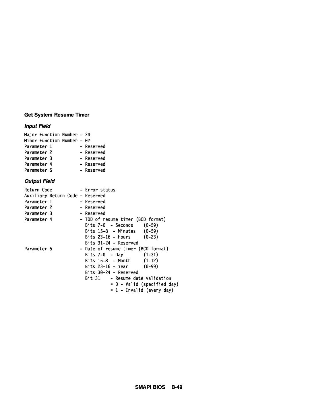
SMAPI BIOS B-49, Input Field, Output Field
Models:
770
1
125
148
148
Download
148 pages
54.66 Kb
122
123
124
125
126
127
128
129
Specifications
Install
Error messages
Signals
Password
Get Timer Control
CMOS RAM Configuration
Hard Disk Drive Connector
Bios
Battery Pack
Page 125
Image 125
Page 124
Page 126
Page 125
Image 125
Page 124
Page 126
Contents
05L1739 S05L-1739-00
Edition
First
System Overview
Contents
Appendix A
Section 3. Subsystems
System Resources
Appendix B. System Management API SMAPI
Management
Index
Page
Supply
Figures
Maximum
Assignments
viii
Preface
x Preface
Section 1. System Overview
1-2 System Overview
Description
computer
IBM Personal System/2 Hardware Interface Technical Reference
System Board Devices and Features
board devices and their features. The
lists the
Figure 1-2 Part 2 of 2. System Board Devices and Features
1-4 System Overview
Figure 1-3 is the I/O address map
System Board I/O Address Map
Device
1-6 System Overview
Address
1-4. Performance Specifications
Specifications
Performance Specifications
1-8 System Overview
Physical Specifications
1-7. Acoustical Readings
Electrical Specifications
1-6. Electrical Specifications
1-10 System Overview
Power Supply
Voltages
Battery Pack
Power Supply Connector
Output Protection
Voltage Sequencing
Figure 1-10. Lithium-ion Battery Pack Specifications
1-12 System Overview
Section 2. System Board
System Board
Microprocessor
Cache Memory Operation
Address
Bus Adapter
Signals
Keyboard/Mouse Connector
Connector
2-4 System Board
Hardware
Scan Codes
Interface
Technical
2-6 System Board
Keyboard ID
Displayable Characters and Symbols
2-8 System Board
Hard Disk Drive Connector
External
Type
2-10 System Board
Signal Name
Signal Name
2-12 System Board
UltraBay
I/O and
Signal
Feature
2-14 System Board
2-9. Diskette Drive
Diskette Drive and Controller
Read
Write
ROM Subsystem
Memory
RAM Subsystem
2-16 System Board
System Memory Map
2-18 System Board
System Board Memory for the DIMM Connectors
Address
RT/CMOS RAM
Bits
NMI Mask Register Hex
0071
2-20 System Board
RT/CMOS
RAM I/O
Operations
Real-Time
2-22 System Board
Clock
000-00D
Status
BitFunction
2-24 System Board
Figure 2-20. Diagnostic
CMOS RAM Configuration
Byte Hex 00E
Status Byte
Diskette Drive Type Byte Hex 010 This byte indicates the type
2-26 System Board
Hard
Disk
Figure 2-28. Installed Diskette Drive Bits
Bits 5
Disk Drive Type
Figure 2-26. Hard Disk Drive Type Byte
Expansion
2-28 System Board
Memory Bytes
Date-Century
Nonmaskable Interrupt NMI
Miscellaneous System Functions and Ports
System Control
Port A Hex
0092
2-30 System Board
System
System/2 and Personal Computer BIOS Interface
0061
System
2-32 System Board
Power-On Password
Other Passwords
Selectable Drive-Startup Sequence
2-34 System Board
Hardware Compatibility
Figure 2-33 Part 1 of 2. Error Codes
Error Codes
Figure 2-33 Part 2 of 2. Error Codes
2-36 System Board
Section 3. Subsystems
3-2 Subsystems
Video Subsystem
Note Use
Alpha
Figure3-1
Buffer
Expanded
Modes-Trident
BIOS
VESA Mode
Monitor
ThinkPad Modem
Modem Subsystem
MIDI Port Function
Sound Blaster Support Function
3-6 Subsystems
Telephony Modem Function
MPC-2
Audio Subsystem
I/O Address
3-8 Subsystems
Audio Port Specifications
Line
DMA Channel
Infrared IR Subsystem
3-10 Subsystems
Video Port Specification
Enhanced Video Subsystem
2 Manufactured by Texas Instruments corporation
PCMCIA Subsystem
same
3-12 Subsystems
Pin Assignments
Ground
PCMCIA PC Card Slot Pin Assignments
MIDI/Joystick Port
IDE Channel on the UltraBay
MIDI Interface
Joystick Interface
Appendix A. System Resources
Page
Resource
Page
Appendix B. System Management API SMAPI BIOS Overview
B-2 SMAPI BIOS
Power Management
System Configuration
SMAPI BIOS B-3
Overview
Image
B-4 SMAPI BIOS
Information Word
SMAPI BIOS B-5
Real Mode Entry Point
16-Bit or 32-Bit Protected
Parameter Structure
B-6 SMAPI BIOS
Calling Convention
Output Field
SMAPI BIOS B-7
Sample in Assembler Language
B-8 SMAPI BIOS
Sample in C Language
SMAPI BIOS B-9
B-10
Calling Convention Pseudo Code
Return Codes
SMAPI BIOS B-11
B-12
Service
Function Description
Get System Identification
Get CPU Information
SMAPI BIOS B-13
Get Display Device
Information
B-14
Get Docking Station
SMAPI BIOS B-15
Information
Get UltraBay
B-16
Get Slave Micro
SMAPI BIOS B-17
Control Unit Information
Get System Sensor
B-18
Get Video Information
SMAPI BIOS B-19
Get Refresh Rate
Capability
B-20
SMAPI BIOS B-21
B-22
System Configuration Service
SMAPI BIOS B-23
B-24
Set Display Device State
Get Pointing Device
SMAPI BIOS B-25
Set Pointing Device
B-26
Get Hotkey
SMAPI BIOS B-27
Set Hotkey Sticky/Lock
B-28
Service
SMAPI BIOS B-29
Power
Set Power Management
B-30
SMAPI BIOS B-31
Get Timer Control
B-32
SMAPI BIOS B-33
Set Timer Control
B-34
Event Bit Definition
Get System Event Global
SMAPI BIOS B-35
Condition
B-36
Set System Event Global Condition
1 Condition
SMAPI BIOS B-37
Get System Event
B-38
Set System Event
1 Condition
2 Condition
SMAPI BIOS B-39
B-40
SMAPI BIOS B-41
Get System Timer
B-42
Set System Timer
Get Hibernation
SMAPI BIOS B-43
B-44
Set Hibernation Timer
3 Condition
SMAPI BIOS B-45
B-46
Get System Resume
SMAPI BIOS B-47
Set System Resume
B-48
SMAPI BIOS B-49
B-50
Standby
SMAPI BIOS B-51
Hibernation
B-52
Data Structure
SMAPI BIOS B-53
Samples
B-54
Parameters
SMBHDRRSEGMENT
SMAPI BIOS B-55
SMBHDRP16OFFSET
SMBHDRP32OFFSET
B-56
Function Declaration
SMAPI BIOS B-57
B-58
Installation Check
SMAPI BIOS B-59
B-60
MyPtr
SMAPI BIOS B-61
B-62
BIOS Call
32-Bit Protected Mode
SMAPI BIOS B-63
MyInput.SMBINSUBFUNC
B-64
Appendix C. Notices
C-2 Notices
Trademarks
Index
X-2 Index
Index
X-4 Index
devicescontinued
boardcontinued
Part Number 05L1739 Printed in the United States of America
Top
Page
Image
Contents