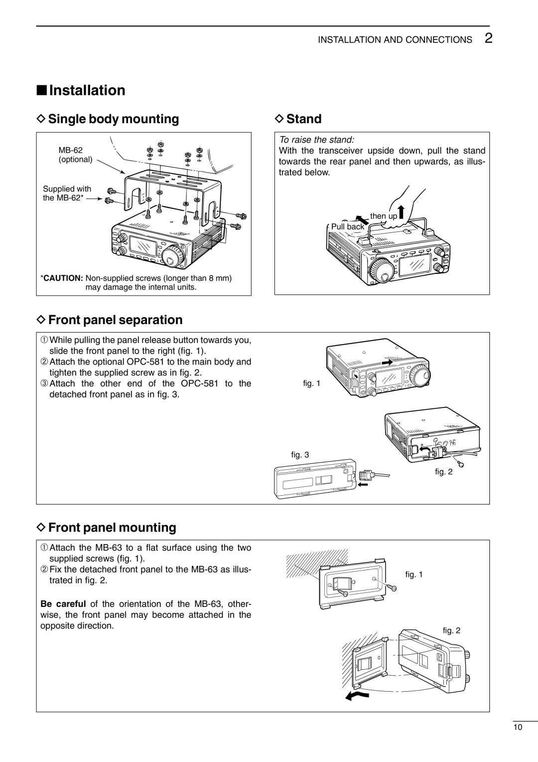
I706MKTMG, IC-706MKIIG specifications
The Icom IC-706MKIIG and the Icom IC-706MKTMG are two prominent transceiver models known for their compact design and versatile capabilities. These radios cater to amateur radio enthusiasts, providing a wide range of features suitable for both HF and VHF/UHF operations.The IC-706MKIIG is a well-regarded dual-band transceiver that operates on HF frequencies from 160 meters to 10 meters and VHF/UHF from 6 meters to 70 centimeters. One of its main features is its compact footprint, making it an excellent choice for mobile operations as well as fixed installation. The transceiver provides up to 100 watts of output power on HF and 50 watts for VHF/UHF, ensuring robust performance for various amateur applications.
On the other hand, the IC-706MKTMG brings the same foundational performance but includes enhanced features aimed at improving user experience. It boasts a high-resolution LCD display with clear visibility under varying light conditions. This model offers advanced digital signal processing (DSP) technology, enhancing audio clarity and reducing noise interference. The built-in auto notch filter and noise blanker efficiently eliminate unwanted signals, allowing users to focus on their desired contacts without distraction.
Both models support multiple modes of operation, including SSB, CW, AM, and FM, which provides versatility in how users can communicate. They feature an easy-to-navigate menu system, allowing users to access settings quickly. With built-in memories and a large number of program settings, operators can customize their experience and quickly switch between configurations.
One standout feature of the IC-706 series is its built-in antenna tuner, which helps match the transceiver to various antenna types, optimizing performance and simplifying setup. The radios also include support for external control via CAT commands, accommodating advanced integration into larger station setups.
In terms of user connectivity, both transceivers come equipped with USB ports and support sound card capabilities, enabling digital modes such as PSK31 and RTTY easily. This integration enhances versatility, catering to modern digital communications alongside traditional voice modes.
Robust, reliable, and feature-rich, the Icom IC-706MKIIG and IC-706MKTMG models stand out as exemplary choices for amateur operators looking for a compact yet comprehensive transceiver solution. Their combination of technologies and characteristics continues to make them popular in the ham radio community.

