10 OPTIONAL INSTALLATIONS/SETTINGS
■UT-106 DSP RECEIVER UNIT
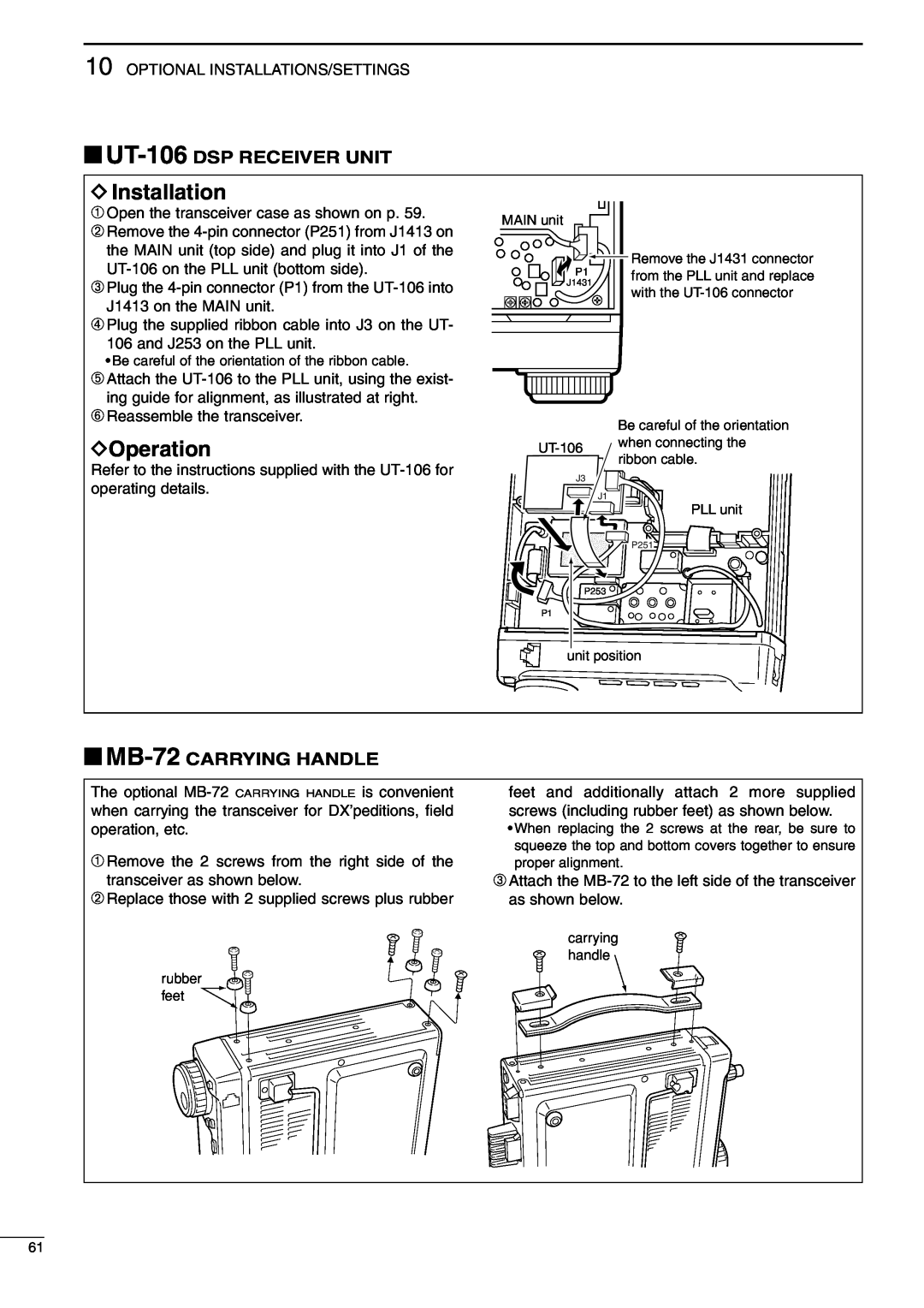
DInstallation
➀Open the transceiver case as shown on p. 59.
➁Remove the
➂Plug the
➃Plug the supplied ribbon cable into J3 on the UT- 106 and J253 on the PLL unit.
•Be careful of the orientation of the ribbon cable.
MAIN unit
P1
![]() J1431
J1431
![]() Remove the J1431 connector from the PLL unit and replace with the
Remove the J1431 connector from the PLL unit and replace with the
➄Attach the
➅Reassemble the transceiver.
DOperation
Refer to the instructions supplied with the
Be careful of the orientation
J3
J1
PLL unit
![]()
![]()
![]()
![]() P251
P251
P253
P1
unit position
■MB-72 CARRYING HANDLE
The optional
➀Remove the 2 screws from the right side of the transceiver as shown below.
➁Replace those with 2 supplied screws plus rubber
rubber feet
feet and additionally attach 2 more supplied screws (including rubber feet) as shown below.
•When replacing the 2 screws at the rear, be sure to squeeze the top and bottom covers together to ensure proper alignment.
➂Attach the
carrying handle
61