IM504
Personal injury, fire or electric shock
Word Definition
May occur
Equipment damage may occur
Case of Emergency
Iii
Determining MPE Radius
Table of Contents
Precautions
OPERATOR’S License
Operating Rules
Radio license for boaters U.S.A. only
Ship Station License
Front panel
Panel Description
2TRANSMIT Power KEY H/L
Function display
0TIME Zone Indicator
2SCAN Indicator
1POSITION Indicator
Microphone
Channel 9 Call channel
Basic Operation
Channel selection
Channel
Rotate Dial to select a channel
S.A., international and Canadian channels
Weather channels
C to change the channel group, if necessary
Receiving and transmitting
While pushing and holding
Call channel programming
Push CH/WXDUAL
Select the desired charac
Channel comments
Microphone Lock function
Display backlight
Activating the scrambler Programming scrambler codes
Optional voice scrambler operation
Dialenter
Normal Scan
Scan Operation
Scan types
Priority Scan
Clearing or setting all tagged channels
Setting TAG channels
Starting a scan
DUALWATCH/TRI-WATCH Simulation
DUALWATCH/TRI-WATCH
Description
Operation
Rotate Dial to set the specific 9-digit Mmsi code
DSC Operation
Mmsi code programming
Rotate Dial to select Mmsi Check, push Dialenter
Check the 9-digit Mmsi DSC self ID code
Mmsi code check
Rotate Dial to set the individual ID and ID name
DSC address ID
Programming Individual ID
Rotate Dial to select AddINDV ID, push Dialenter
Rotate Dial to select Delindv ID, push Dialenter
Deleting Individual ID
Rotate Dial to select the desired ID name for deleting
Rotate Dial to select AddGroup ID, push Dialenter
Programming Group ID
Rotate Dial to set the group ID and ID name
Rotate Dial to select DELGroup ID, push Dialenter
Deleting Group ID
Position and time programming
GPS information indication
Position and time indication
Simple call
Distress call
After 2 sec. Wait ACK
Regular call
Distress alert contains default
Push Distress for 5 sec. to transmit the distress call
Transmitting an individual call
Transmitting DSC calls
Push Dialenter to transmit the individual call
Transmitting an individual acknowledgement
Transmitting a group call
Push Dialenter to transmit the group call
Rotate Dial to select the desired category, push Dialenter
Transmitting an all ships call
Push Dialenter to transmit the all ships call
Transmitting a position request call
Push Dialenter to transmit the position request call
Transmitting a position report call
Push Dialenter to transmit the position report call
Push Dialenter to transmit the polling request call
Transmitting a polling request call
Transmitting a position request reply call
Your position data is transmitted, when Dialenter is pushed
Transmitting a position report reply call
Transmitting a polling request reply call
Receiving a distress relay call
Receiving DSC calls
Receiving a distress call
Receiving a distress acknowledgement
Receiving a group call
Receiving an individual call
Receiving an all ships call
Receiving a position request call
Receiving a geographical area call
Receiving a position report call
Receiving a polling request reply call
Receiving a polling request call
Receiving a position request reply call
Receiving a position report reply call
Rotate Dial to scroll the message
Received messages
Distress message
Rotate Dial to select Distress, push Dialenter
Rotate Dial to select Other, push Dialenter
Other messages
No offset time default
DSC Set mode
Rotate Dial to select Offset Time, push Dialenter
Rotate Dial to select Auto ACK, push
Automatic acknowledgement
Push Dialenter to set the condition
Rotate Dial to select Nmea Output, push Dialenter
Nmea Output
Intercom operation
Other Functions
HM-162 listener
RX Speaker function
Hailer operation
Push Hailrx to enter hailer mode
To return to normal operation, push CLR or Hailrx
Sail
Automatic foghorn function
Underway
Stop
Tion is interrupted with an automatic return to the trans
Rotate Dial to adjust the foghorn level, push Dialenter
Ing DSC calls.’ p
Scan resume timer
SET Mode
Set mode programming
Set mode items
LCD contrast
Weather alert
Dual/Tri-watch
Beep tone
Scrambler code
Radio power
Automatic foghorn frequency
Scrambler type
0DC Power Connector
Connections and Maintenance
Connections
Supplied accessories
Fuse replacement
Antenna
Mounting the transceiver
Using the supplied mounting bracket
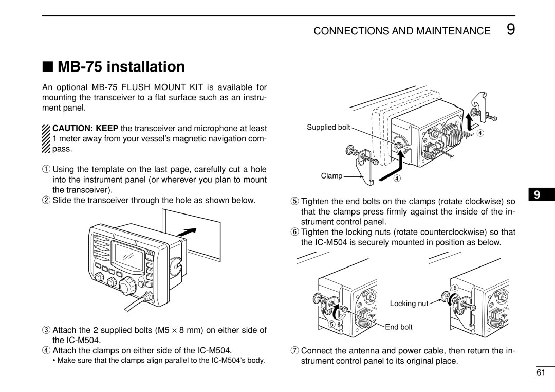
Tighten the end bolts on the clamps rotate clockwise so
MB-75 installation
That the clamps press firmly against the inside
UT-112/UT-98 installation
Return the cables and screws to the original position
HM-162/HM-157 installation
HM-162 HM-157
Completed installation should look like this
HM-162
HM-157
Gasket
Mm 131⁄32˝ Nut Cap
Problem Possible Cause Solution
Troubleshooting
Transmitter
Specifications and Options
Specifications
General Receiver
20 feet microphone extension cable for optional HM
Dimensions
Options
For mounting the transceiver to a panel
Transmit Receive
Channel List
R12 Max
Template
Unit mm inch Cut here
Page
Memo
Kamiminami, Hirano-ku, Osaka 547-0003, Japan