7000 Series Bus Converter
7000 series overview
Common Features of the 7000 Series
Dimension
7520 Pin Assignment and Specifications Block Diagram
7513
7510
Quick Starting the 7000 Series
PC Networking Applications RS-232 Devices Network
Introduction
Group 10 Power supply module ACE-540A 24V/2A power supply
Page
Page
Page
Page
Back View
Stack Mounting Din Rail Mounting
Isolation voltage
7520/A/R/AR, PCI-7520AR, PCISA-7520R
Remove resistor
3 I-7520 is designed Termination resistor 120 Ohm on board
7520R RS-232 to RS-485 Converter
I-7520R Pin Assignment and Specifications
7520A RS-232 to RS-422/485 Converter
I-7520A Pin Assignment and Specifications
JP1
Default sitting Ohm on board
JP3
7520AR RS-232 to RS-422/485 Converter
I-7520AR Pin Assignment and Specifications
PCI-7520AR Pin Assignment and Specification
Terminal Wire RS-485 Wire RS-422
Not Connect
Terminal Wire RS-485
PCISA-7520R Pin Assignment and Specification
7000 Host Computer 7520
Page
Network
Therefore the Host PC/PLC is common ground with
If there is high voltage
Power Ground with Host PC/PLC for
Uses the same DC
Host PC/PLC
Configuration B
7560 / I-7561
Introduction
I-7560 Pin Assignment and Specifications
I-7560 System Network Configuration Block Diagram
Installing the Device
3 I-7560 Driver Installation
Page
Page
Page
Page
Page
Page
Page
Specifications
I-7561 Pin Assignment and Specifications
Page
4 I-7561 is designed Termination resistor 120 Ohm on board
Set Type Channels RS-485
JP3
Page
Page
Page
Page
Page
Page
Page
Page
Page
Page
Page
Page
7563
I-7563 Pin Assignment and Specifications
Page
Page
Page
Page
Page
Page
Page
Page
Page
RS-232 TxD, RxD, CTS, RTS, GND or TxD, RxD, DCD, DTR, GND
I-7551 Pin Assignment and Specifications
Page
7510 / I-7510A / I-7510AR
7510A RS-485/RS-422 Repeater
I-7510A Pin Assignment and Specifications
7510AR
I-7510AR Pin Assignment and Specifications
Page
7513
Page
Page
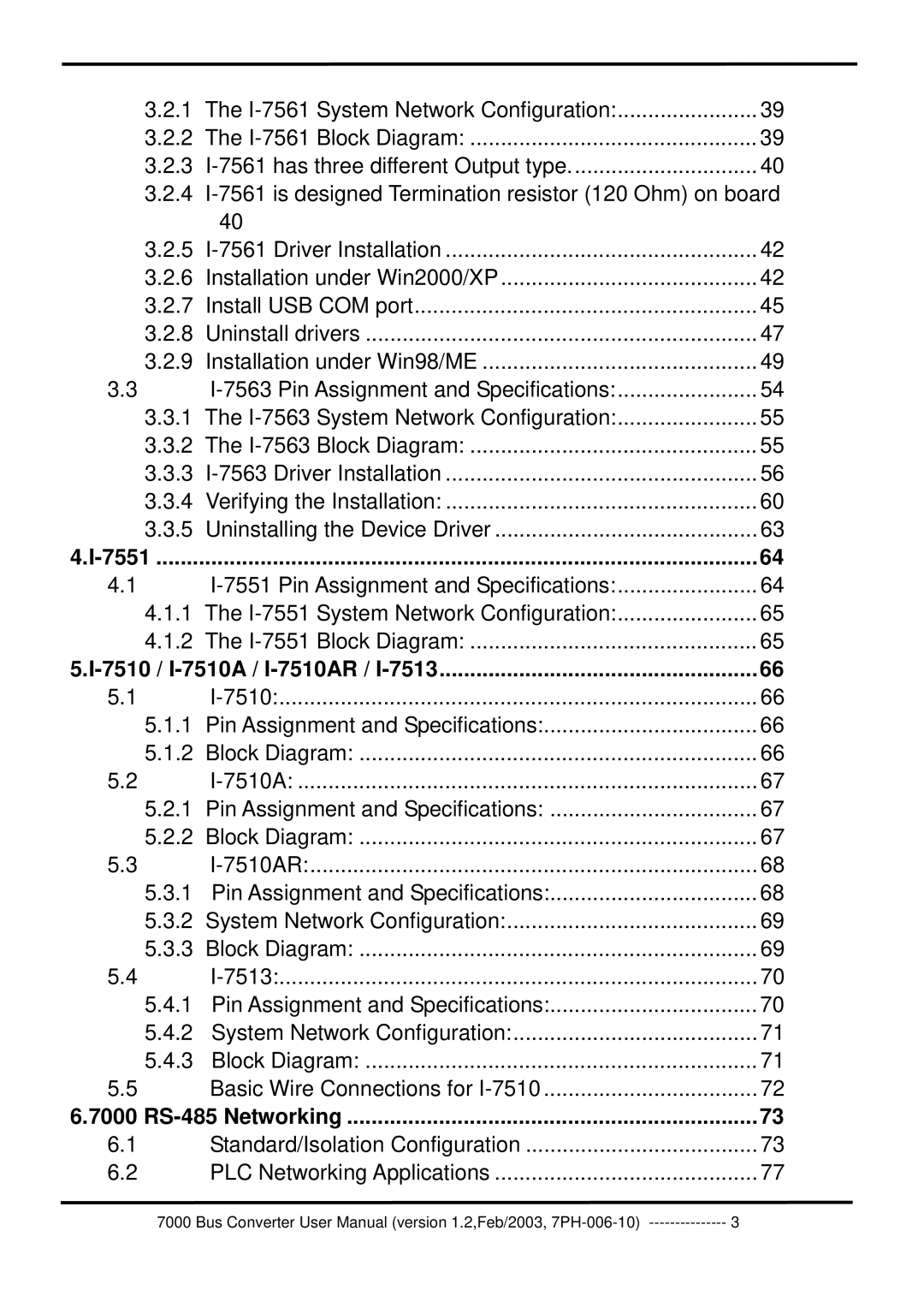
RS-485 Networking
This is the third function
GND
Page
RS2
PLC Networking Applications
PC Networking Applications
RS-485 Series 7520 Host PC RS-232 device
Quick Starting the 7000 Series
Find Status of Unknown Module Wire connection Refer to Sec
Press $02FEnter
Changing Module Address Wire connection Refer to Sec
Changing Baud Rate Wire connection Refer to Sec
Press $012Enter Receive=!01080640B1
Checksum Enable/Disable Wire connection Refer to Sec
Checksum=0

