STEP 7 (See Diagram 7)
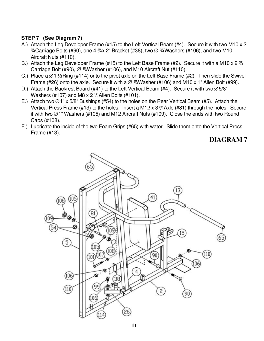
A.) Attach the Leg Developer Frame (#15) to the Left Vertical Beam (#4). Secure it with two M10 x 2 ¾” Carriage Bolts (#90), one 4 ¾” x 2” Bracket (#38), two ∅ ¾” Washers (#106), and two M10 Aircraft Nuts (#110).
B.) Attach the Leg Developer Frame (#15) to the Left Base Frame (#2). Secure it with a M10 x 2 ¾” Carriage Bolt (#90), ∅ ¾” Washer (#106), and M10 Aircraft Nut (#110).
C.) Place a ∅1 ½” Ring (#114) onto the pivot axle on the Left Base Frame (#2). Then slide the Swivel Frame (#26) onto the axle. Secure it with a ∅ ¾” Washer (#106) and M10 x 1” Allen Bolt (#99).
D.) Attach the Backrest Board (#41) to the Left Vertical Beam (#4). Secure it with two ∅5/8” Washers (#107) and M8 x 2 ½” Allen Bolts (#101).
E.) Attach two ∅1” x 5/8” Bushings (#54) to the holes on the Rear Vertical Beam (#5). Attach the Vertical Press Frame (#13) to the holes. Insert a M12 x 3 ¾” Axle (#81) through the holes. Secure it with two ∅1” Washers (#105) and M12 Aircraft Nuts (#109). Close the ends with two Round Caps (#108).
F.) Lubricate the inside of the two Foam Grips (#65) with water. Slide them onto the Vertical Press Frame (#13).
DIAGRAM 7
11