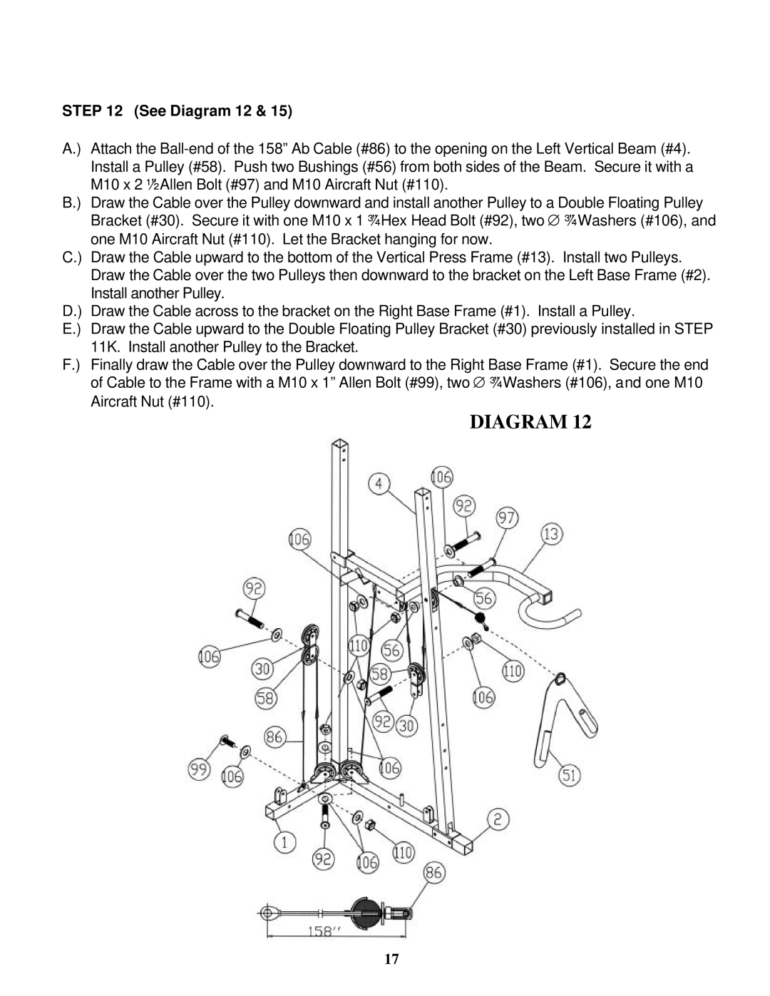
STEP 12 (See Diagram 12 & 15)
A.) Attach the
B.) Draw the Cable over the Pulley downward and install another Pulley to a Double Floating Pulley Bracket (#30). Secure it with one M10 x 1 ¾” Hex Head Bolt (#92), two ∅ ¾” Washers (#106), and one M10 Aircraft Nut (#110). Let the Bracket hanging for now.
C.) Draw the Cable upward to the bottom of the Vertical Press Frame (#13). Install two Pulleys. Draw the Cable over the two Pulleys then downward to the bracket on the Left Base Frame (#2). Install another Pulley.
D.) Draw the Cable across to the bracket on the Right Base Frame (#1). Install a Pulley.
E.) Draw the Cable upward to the Double Floating Pulley Bracket (#30) previously installed in STEP 11K. Install another Pulley to the Bracket.
F.) Finally draw the Cable over the Pulley downward to the Right Base Frame (#1). Secure the end of Cable to the Frame with a M10 x 1” Allen Bolt (#99), two ∅ ¾” Washers (#106), and one M10 Aircraft Nut (#110).
DIAGRAM 12
17