STEP 10 (See Diagram 10 & 15)
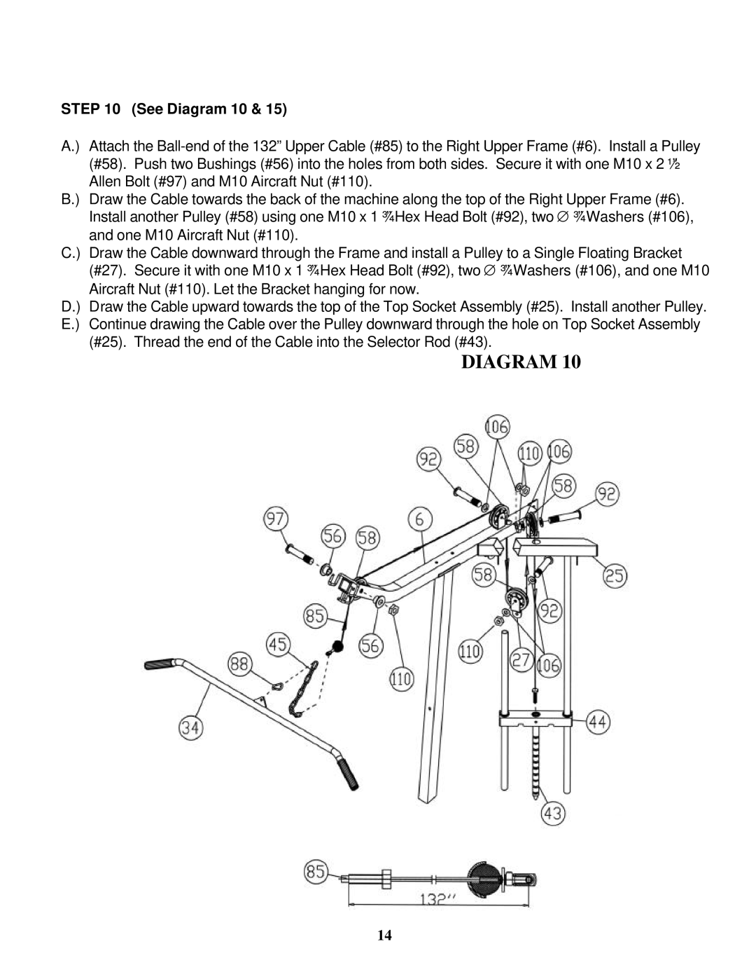
A.) Attach the
B.) Draw the Cable towards the back of the machine along the top of the Right Upper Frame (#6). Install another Pulley (#58) using one M10 x 1 ¾” Hex Head Bolt (#92), two ∅ ¾” Washers (#106), and one M10 Aircraft Nut (#110).
C.) Draw the Cable downward through the Frame and install a Pulley to a Single Floating Bracket (#27). Secure it with one M10 x 1 ¾” Hex Head Bolt (#92), two ∅ ¾” Washers (#106), and one M10 Aircraft Nut (#110). Let the Bracket hanging for now.
D.) Draw the Cable upward towards the top of the Top Socket Assembly (#25). Install another Pulley. E.) Continue drawing the Cable over the Pulley downward through the hole on Top Socket Assembly
(#25). Thread the end of the Cable into the Selector Rod (#43).
DIAGRAM 10
14