STEP 5 (See Diagram 5)
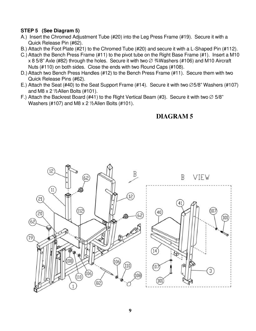
A.) Insert the Chromed Adjustment Tube (#20) into the Leg Press Frame (#19). Secure it with a Quick Release Pin (#62).
B.) Attach the Foot Plate (#21) to the Chromed Tube (#20) and secure it with a
Nuts (#110) on both sides. Close the ends with two Round Caps (#108).
D.) Attach two Bench Press Handles (#12) to the Bench Press Frame (#11). Secure them with two Quick Release Pins (#62).
E.) Attach the Seat (#40) to the Seat Support Frame (#14). Secure it with two ∅5/8” Washers (#107) and M8 x 2 ½” Allen Bolts (#101).
F.) Attach the Backrest Board (#41) to the Right Vertical Beam (#3). Secure it with two ∅ 5/8” Washers (#107) and M8 x 2 ½” Allen Bolts (#101).
DIAGRAM 5
9