STEP 4 (See Diagram 4)
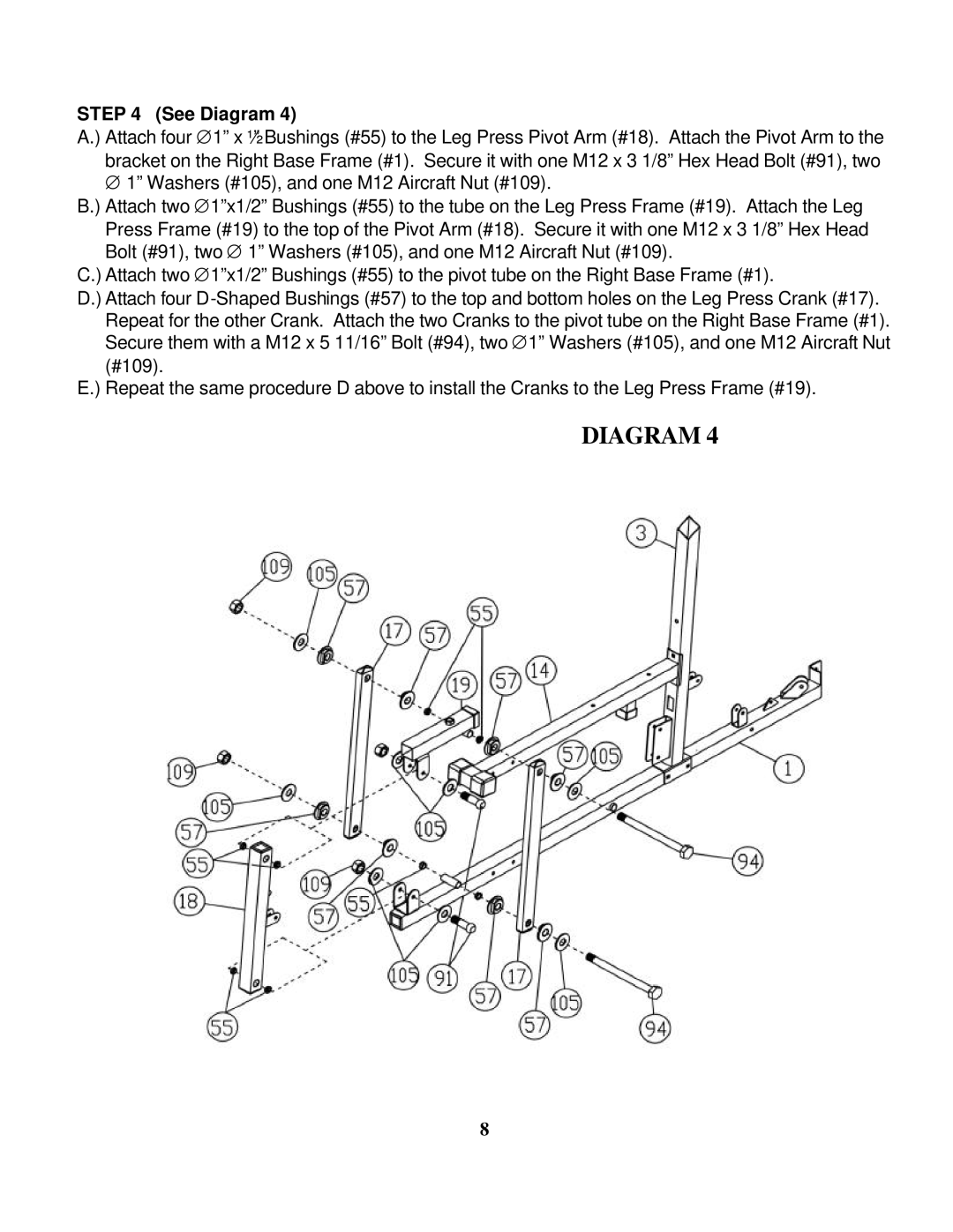
A.) Attach four ∅1” x ½” Bushings (#55) to the Leg Press Pivot Arm (#18). Attach the Pivot Arm to the bracket on the Right Base Frame (#1). Secure it with one M12 x 3 1/8” Hex Head Bolt (#91), two
∅1” Washers (#105), and one M12 Aircraft Nut (#109).
B.) Attach two ∅1”x1/2” Bushings (#55) to the tube on the Leg Press Frame (#19). Attach the Leg Press Frame (#19) to the top of the Pivot Arm (#18). Secure it with one M12 x 3 1/8” Hex Head Bolt (#91), two ∅ 1” Washers (#105), and one M12 Aircraft Nut (#109).
C.) Attach two ∅1”x1/2” Bushings (#55) to the pivot tube on the Right Base Frame (#1).
D.) Attach four
E.) Repeat the same procedure D above to install the Cranks to the Leg Press Frame (#19).
DIAGRAM 4
8