ASSEMBLY INSTRUCTION
Tools Required to Assemble the Machine: Two Adjustable Wrenches and Allen Wrenches
NOTE: It is strongly recommended this machine be assembled by two or more people to avoid possible injury.
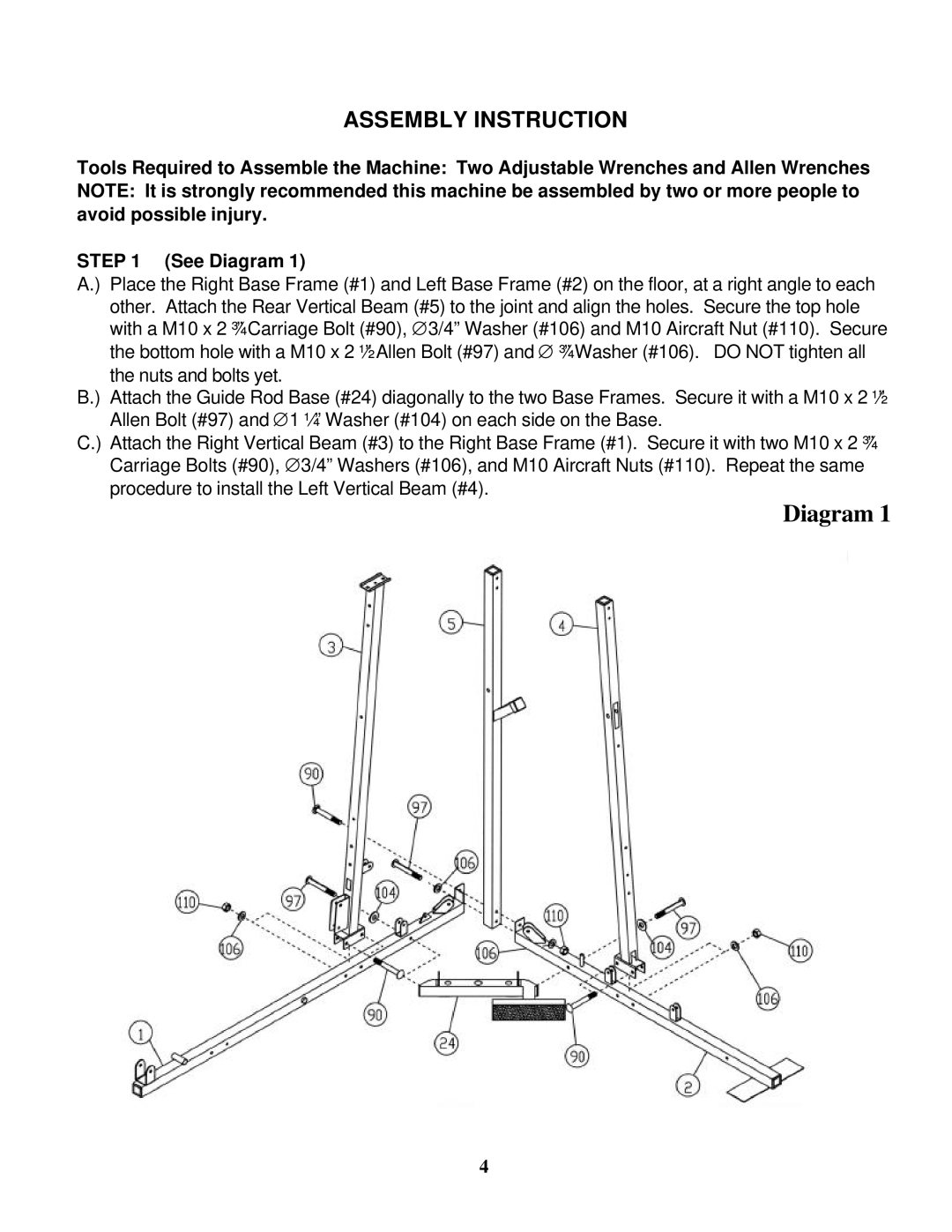
STEP 1 (See Diagram 1)
A.) Place the Right Base Frame (#1) and Left Base Frame (#2) on the floor, at a right angle to each other. Attach the Rear Vertical Beam (#5) to the joint and align the holes. Secure the top hole with a M10 x 2 ¾” Carriage Bolt (#90), ∅3/4” Washer (#106) and M10 Aircraft Nut (#110). Secure the bottom hole with a M10 x 2 ½” Allen Bolt (#97) and ∅ ¾” Washer (#106). DO NOT tighten all the nuts and bolts yet.
B.) Attach the Guide Rod Base (#24) diagonally to the two Base Frames. Secure it with a M10 x 2 ½” Allen Bolt (#97) and ∅1 ¼” Washer (#104) on each side on the Base.
C.) Attach the Right Vertical Beam (#3) to the Right Base Frame (#1). Secure it with two M10 x 2 ¾” Carriage Bolts (#90), ∅3/4” Washers (#106), and M10 Aircraft Nuts (#110). Repeat the same procedure to install the Left Vertical Beam (#4).
Diagram 1
4