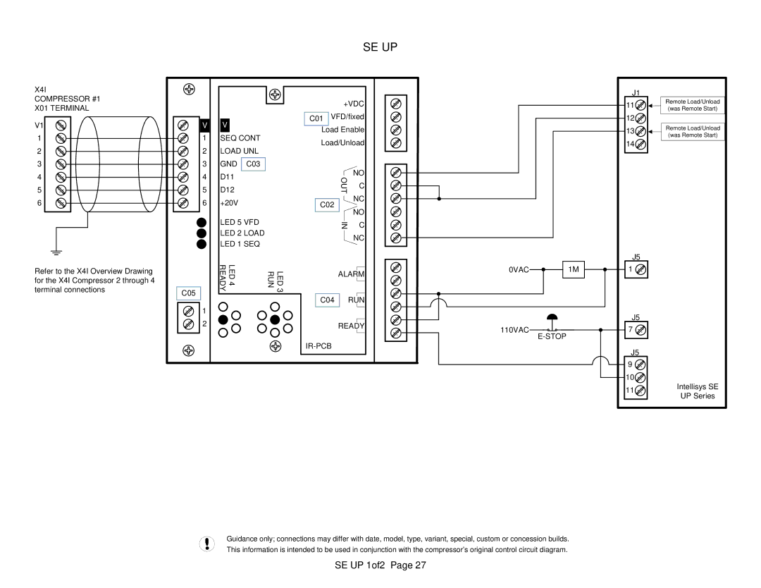
X4I
COMPRESSOR #1
X01 TERMINAL
V1
1
2
3
4
5
6
Refer to the X4I Overview Drawing for the X4I Compressor 2 through 4 terminal connections
SE UP
|
|
|
| +VDC | ||
V | V |
| C01 VFD/fixed | |||
| Load Enable | |||||
1 | SEQ CONT | |||||
Load/Unload | ||||||
2 | LOAD UNL | |||||
|
|
| ||||
3 | GND | C03 |
|
| NO | |
4 | D11 |
|
| OUT | ||
|
| C | ||||
5 | D12 |
|
| |||
6 | +20V |
| C02 |
| NC | |
|
| NO | ||||
|
|
|
|
| ||
| LED 5 VFD |
| IN | C | ||
| LED 2 LOAD |
| ||||
|
|
| NC | |||
| LED 1 SEQ |
|
| |||
|
|
|
| |||
| LED4 READY | RUN | LED3 | ALARM | ||
|
|
|
| |||
C05 |
|
| C04 | RUN | ||
|
|
| ||||
1 |
|
|
|
|
| |
2 |
|
|
| READY | ||
|
|
|
|
| ||
0VAC  1M
1M
110VAC 

J1
11![]()
![]()
12![]()
13![]()
![]()
14![]()
J5
1 ![]()
![]()
J5
7 ![]()
![]()
J5
9 ![]()
10![]()
11![]()
Remote Load/Unload (was Remote Start)
Remote Load/Unload (was Remote Start)
Intellisys SE
UP Series
Guidance only; connections may differ with date, model, type, variant, special, custom or concession builds. This information is intended to be used in conjunction with the compressor’s original control circuit diagram.