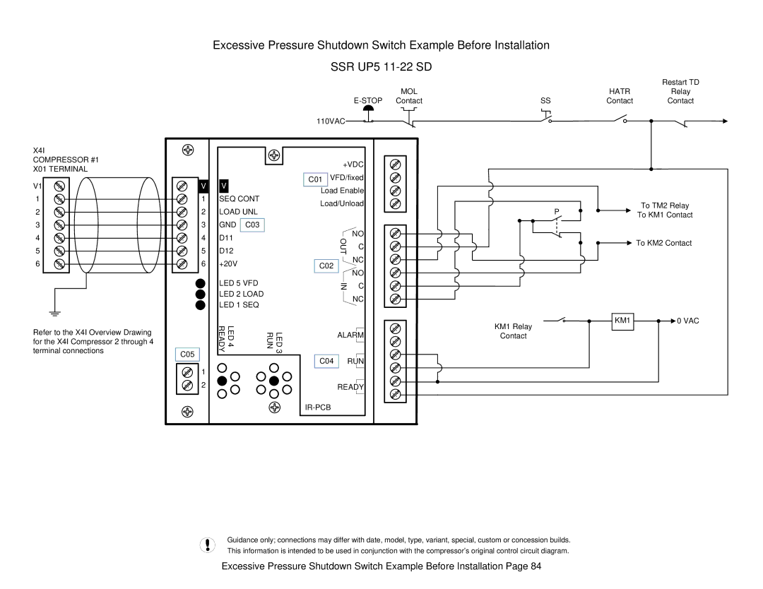
X4I
COMPRESSOR #1
X01 TERMINAL
V1
1
2
3
4
5
6
Refer to the X4I Overview Drawing for the X4I Compressor 2 through 4 terminal connections
C05
| Excessive Pressure Shutdown Switch Example Before Installation |
|
| ||||||
|
|
| SSR UP5 |
|
|
| |||
|
|
|
|
|
| MOL |
| HATR | Restart TD |
|
|
|
|
|
| Relay | |||
|
|
|
|
| Contact | SS | Contact | Contact | |
|
|
| 110VAC |
|
|
|
|
| |
|
|
|
| +VDC |
|
|
|
| |
V | V |
| C01 VFD/fixed |
|
|
|
| ||
| Load Enable |
|
|
|
| ||||
1 | SEQ CONT |
|
|
|
| ||||
Load/Unload |
|
|
| To TM2 Relay | |||||
2 | LOAD UNL |
|
| P | |||||
|
|
|
|
| To KM1 Contact | ||||
3 | GND | C03 |
|
|
|
|
|
| |
|
| NO |
|
|
|
| |||
4 | D11 |
|
| OUT |
|
|
| To KM2 Contact | |
|
| C |
|
|
| ||||
5 | D12 |
|
|
|
|
| |||
|
|
|
|
|
|
|
|
| |
6 | +20V |
| C02 |
| NC |
|
|
|
|
|
| NO |
|
|
|
| |||
|
|
|
|
|
|
|
|
| |
| LED 5 VFD |
| IN | C |
|
|
|
| |
| LED 2 LOAD |
|
|
|
|
| |||
|
|
| NC |
|
|
|
| ||
| LED 1 SEQ |
|
|
|
|
|
| ||
|
|
|
|
|
|
|
| ||
| LED4 READY |
|
|
|
|
| KM1 Relay | KM1 | 0 VAC |
| RUN | LED3 | ALARM |
|
|
| |||
|
| Contact |
|
| |||||
|
|
|
|
|
|
| |||
|
|
| C04 | RUN |
|
|
|
| |
1 |
|
|
|
|
|
|
|
|
|
2 |
|
|
| READY |
|
|
|
| |
|
|
|
|
|
|
|
|
| |
Guidance only; connections may differ with date, model, type, variant, special, custom or concession builds. This information is intended to be used in conjunction with the compressor’s original control circuit diagram.
Excessive Pressure Shutdown Switch Example Before Installation Page 84