compressor number) with an additional wire. Use a 7- conductor shielded cable in this instance.
![]() Compressors that use electronic pressure detection but are not equipped with a remote pressure control enable feature will not automatically revert to local control if the X4I is stopped or experiences a fault or loss of power.
Compressors that use electronic pressure detection but are not equipped with a remote pressure control enable feature will not automatically revert to local control if the X4I is stopped or experiences a fault or loss of power.
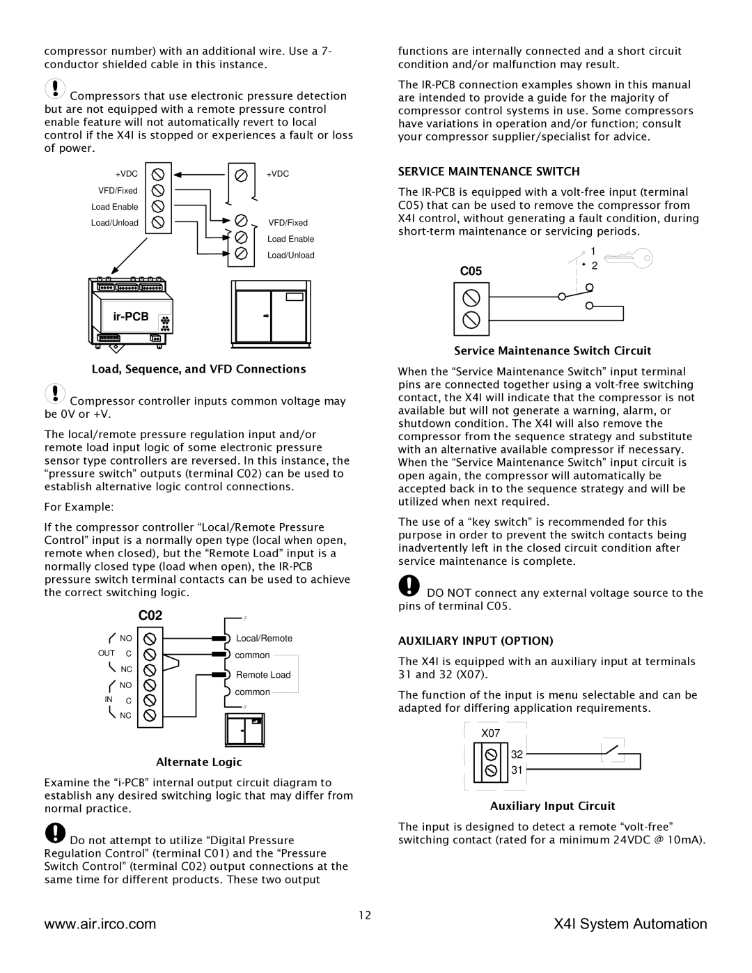
+VDC | +VDC |
VFD/Fixed |
|
Load Enable |
|
Load/Unload | VFD/Fixed |
| Load Enable |
| Load/Unload |
Load, Sequence, and VFD Connections
![]() Compressor controller inputs common voltage may be 0V or +V.
Compressor controller inputs common voltage may be 0V or +V.
The local/remote pressure regulation input and/or remote load input logic of some electronic pressure sensor type controllers are reversed. In this instance, the “pressure switch” outputs (terminal C02) can be used to establish alternative logic control connections.
For Example:
If the compressor controller “Local/Remote Pressure Control” input is a normally open type (local when open, remote when closed), but the “Remote Load” input is a normally closed type (load when open), the
functions are internally connected and a short circuit condition and/or malfunction may result.
The
SERVICE MAINTENANCE SWITCH
The
| 1 |
C05 | 2 |
|
Service Maintenance Switch Circuit
When the “Service Maintenance Switch” input terminal pins are connected together using a
The use of a “key switch” is recommended for this purpose in order to prevent the switch contacts being inadvertently left in the closed circuit condition after service maintenance is complete.
![]() DO NOT connect any external voltage source to the pins of terminal C05.
DO NOT connect any external voltage source to the pins of terminal C05.
C02
NO
OUT C
NC
NO
IN C
NC
Local/Remote common
Remote Load ![]() common
common
AUXILIARY INPUT (OPTION)
The X4I is equipped with an auxiliary input at terminals 31 and 32 (X07).
The function of the input is menu selectable and can be adapted for differing application requirements.
X07
Alternate Logic
Examine the
![]() Do not attempt to utilize “Digital Pressure Regulation Control” (terminal C01) and the “Pressure Switch Control” (terminal C02) output connections at the same time for different products. These two output
Do not attempt to utilize “Digital Pressure Regulation Control” (terminal C01) and the “Pressure Switch Control” (terminal C02) output connections at the same time for different products. These two output
32
31
Auxiliary Input Circuit
The input is designed to detect a remote
www.air.irco.com | 12 | X4I System Automation |
|