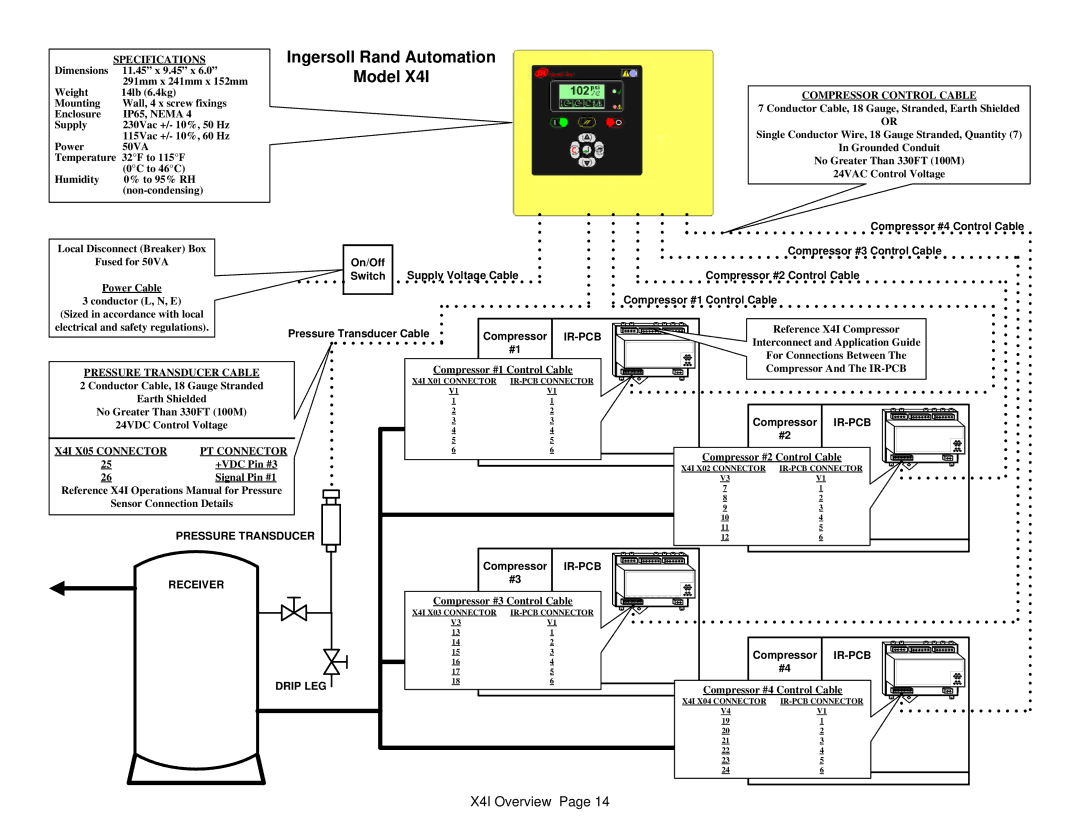
Dimensions | SPECIFICATIONS |
11.45” x 9.45” x 6.0” | |
Weight | 291mm x 241mm x 152mm |
14lb (6.4kg) | |
Mounting | Wall, 4 x screw fixings |
Enclosure | IP65, NEMA 4 |
Supply | 230Vac +/- 10%, 50 Hz |
Power | 115Vac +/- 10%, 60 Hz |
50VA | |
Temperature 32°F to 115°F | |
Humidity | (0°C to 46°C) |
0% to 95% RH | |
| |
Ingersoll Rand Automation
Model X4I
COMPRESSOR CONTROL CABLE
7 Conductor Cable, 18 Gauge, Stranded, Earth Shielded
OR
Single Conductor Wire, 18 Gauge Stranded, Quantity (7)
In Grounded Conduit
No Greater Than 330FT (100M)
24VAC Control Voltage
Compressor #4 Control Cable
Local Disconnect (Breaker) Box | On/Off |
|
|
|
|
| Compressor #3 Control Cable | |
Fused for 50VA |
| Supply Voltage Cable |
| Compressor #2 Control Cable | ||||
Power Cable |
| Switch |
| |||||
|
|
|
|
|
| Compressor #1 Control Cable | ||
3 conductor (L, N, E) |
|
|
|
|
| |||
(Sized in accordance with local |
|
|
|
|
|
|
| |
electrical and safety regulations). | Pressure Transducer Cable | Compressor |
|
| Reference X4I Compressor | |||
|
| Interconnect and Application Guide | ||||||
|
|
|
|
| #1 |
| ||
|
|
|
|
|
|
| For Connections Between The | |
|
|
|
|
|
|
|
| |
PRESSURE TRANSDUCER CABLE |
|
| Compressor #1 Control Cable |
| Compressor And The | |||
2 Conductor Cable, 18 Gauge Stranded |
| X4I X01 CONNECTOR |
|
| ||||
|
| V1 | V1 |
|
|
| ||
Earth Shielded |
|
|
|
|
| |||
|
| 1 | 1 |
|
|
| ||
No Greater Than 330FT (100M) |
|
| 2 | 2 |
|
|
| |
24VDC Control Voltage |
|
| 3 | 3 |
| Compressor | ||
|
| 4 | 4 |
| ||||
|
|
|
|
|
| #2 | ||
X4I X05 CONNECTOR | PT CONNECTOR |
|
| 5 | 5 |
|
| |
|
| 6 | 6 |
| Compressor #2 Control Cable | |||
25 | +VDC Pin #3 |
|
|
|
|
| ||
|
|
|
|
| X4I X02 CONNECTOR | |||
26 | Signal Pin #1 |
|
|
|
|
| V3 | V1 |
Reference X4I Operations Manual for Pressure |
|
|
|
|
| 7 | 1 | |
Sensor Connection Details |
|
|
|
|
| 8 | 2 | |
|
|
|
|
| 9 | 3 | ||
|
|
|
|
|
|
| 10 | 4 |
| PRESSURE TRANSDUCER |
|
|
|
| 11 | 5 | |
|
|
|
|
| 12 | 6 | ||
|
|
|
| Compressor |
|
| ||
RECEIVER |
|
|
| #3 |
|
|
| |
|
|
|
|
|
|
| ||
|
|
|
| Compressor #3 Control Cable |
|
| ||
|
|
| X4I X03 CONNECTOR |
|
| |||
|
|
|
| V3 | V1 |
|
|
|
|
|
|
|
| 13 |
| 1 |
|
|
|
|
|
|
|
|
|
|
|
|
|
|
|
|
|
|
|
|
|
|
|
|
|
|
| |
|
|
|
|
| 14 |
| 2 |
|
|
|
|
|
|
|
|
|
|
|
|
|
|
|
|
|
|
|
|
|
|
|
|
|
|
| |
|
|
|
|
| 15 |
| 3 |
|
|
|
| Compressor |
|
|
|
|
|
|
|
|
|
|
|
|
|
|
|
| |||||||
|
|
|
|
| 16 |
| 4 |
|
|
|
|
| #4 |
|
|
|
|
|
|
|
|
|
|
|
|
|
|
|
|
|
|
|
| ||
|
|
|
|
| 17 |
| 5 |
|
|
|
|
|
|
|
|
|
|
|
|
|
|
|
|
|
|
|
|
|
|
|
|
| |||
|
| DRIP LEG |
|
| 18 |
| 6 |
|
| Compressor |
| #4 Control | Cable |
|
|
|
|
|
|
|
|
|
|
|
|
|
|
|
| ||||||
|
|
|
|
|
|
|
|
|
|
|
|
|
|
|
|
|
|
|
|
|
|
| |||||||||||||
|
|
|
|
|
|
|
|
| X4I | X04 CONNECTOR | CONNECTOR |
|
|
|
|
|
|
|
|
|
|
|
|
|
|
| |||||||||
|
|
|
|
|
|
|
|
|
|
| V4 |
|
| V1 |
| ||||||||||||||||||||
|
|
|
|
|
|
|
|
| |||||||||||||||||||||||||||
|
|
|
|
|
|
|
|
| 19 |
|
|
| 1 |
|
|
|
|
|
|
|
|
|
|
|
|
|
|
|
|
|
| ||||
|
|
|
|
|
|
|
|
| 20 |
|
| 2 |
|
|
|
|
|
|
|
|
|
|
|
|
|
|
|
|
|
| |||||
|
|
|
|
|
|
|
|
| 21 |
|
| 3 |
|
|
|
|
|
|
|
|
|
|
|
|
|
|
|
|
|
| |||||
|
|
|
|
|
|
|
|
| 22 |
|
| 4 |
|
|
|
|
|
|
|
|
|
|
|
|
|
|
|
|
|
| |||||
|
|
|
|
|
|
|
|
| 23 |
|
| 5 |
|
|
|
|
|
|
|
|
|
|
|
|
|
|
|
|
|
| |||||
|
|
|
|
|
|
|
|
| 24 |
|
| 6 |
|
|
|
|
|
|
|
|
|
|
|
|
|
|
|
|
|
| |||||
|
|
|
|
|
|
|
|
|
|
|
|
|
|
|
|
|
|
|
|
|
|
|
|
|
|
|
|
|
|
|
|
|
|
|
|