PRESSURE SENSOR CONNECTION
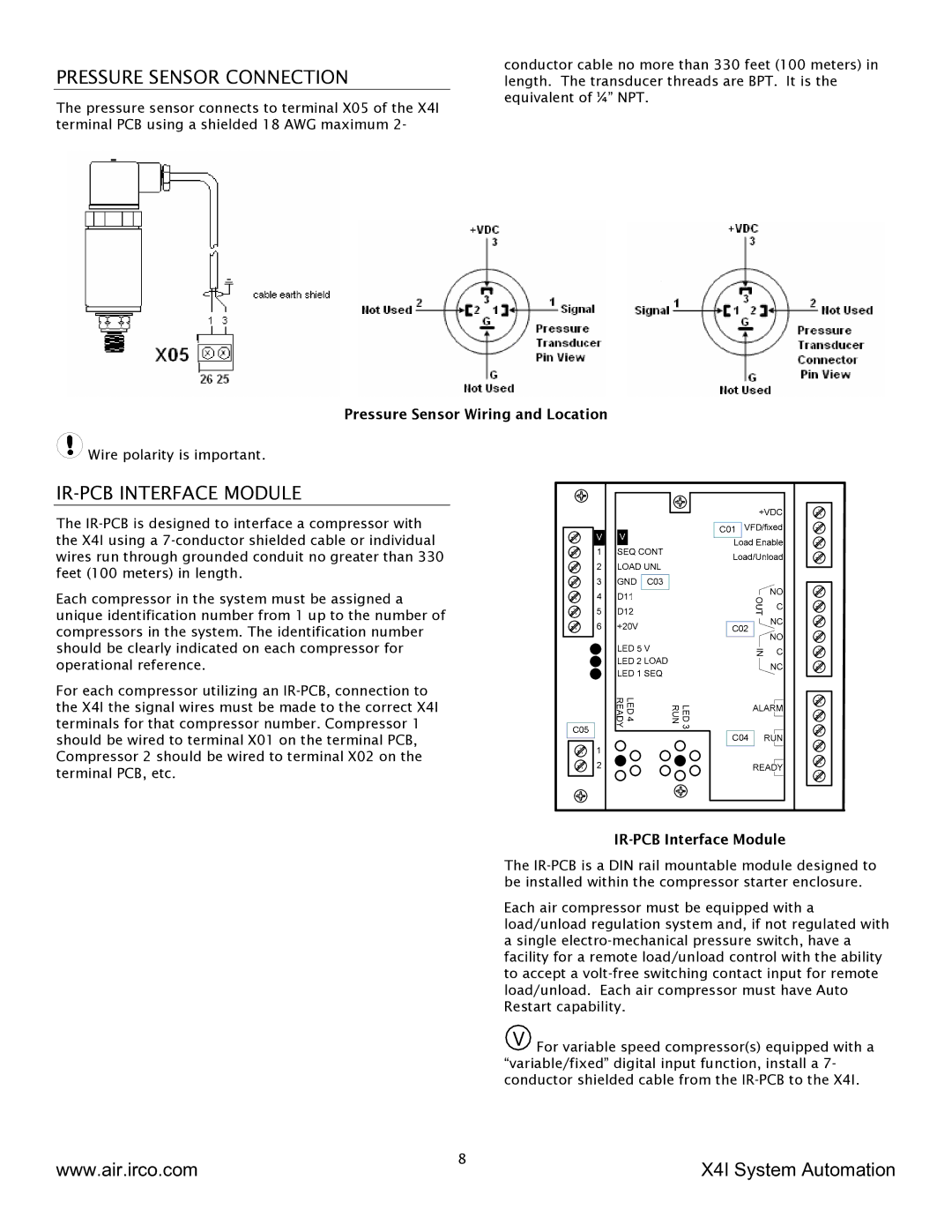
The pressure sensor connects to terminal X05 of the X4I terminal PCB using a shielded 18 AWG maximum 2-
conductor cable no more than 330 feet (100 meters) in length. The transducer threads are BPT. It is the equivalent of ¼” NPT.
Pressure Sensor Wiring and Location
![]() Wire polarity is important.
Wire polarity is important.
IR-PCB INTERFACE MODULE
The
Each compressor in the system must be assigned a unique identification number from 1 up to the number of compressors in the system. The identification number should be clearly indicated on each compressor for operational reference.
For each compressor utilizing an
IR-PCB Interface Module
The
Each air compressor must be equipped with a load/unload regulation system and, if not regulated with a single
V For variable speed compressor(s) equipped with a “variable/fixed” digital input function, install a 7- conductor shielded cable from the
www.air.irco.com | 8 | X4I System Automation |
|