![]() Consult the air compressor manual or your air compressor supplier/specialist for details before installing the X4I.
Consult the air compressor manual or your air compressor supplier/specialist for details before installing the X4I.
Each air compressor must be equipped with an online/offline pressure regulation system capable of accepting a remote load/unload signal through a volt free switching contact or a single
The
![]() Consult the X4I Interconnect and Application Guide prior to the installation of the X4I and the
Consult the X4I Interconnect and Application Guide prior to the installation of the X4I and the
INPUT FUNCTIONS
The
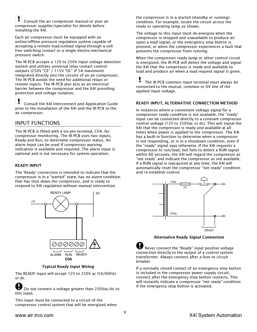
READY INPUT
The ‘Ready’ connection is intended to indicate that the compressor is in a “started” state, has no alarm condition that has shut down the compressor, and is ready to respond to X4I regulation without manual intervention.
READY LAMP | 0V |
+V
ALARM RUN READY
C04
Typical Ready Input Wiring
The READY input will accept 12V to 250V ac (50/60Hz) or dc.
![]() Do not connect a voltage greater than 250Vac/dc to this input.
Do not connect a voltage greater than 250Vac/dc to this input.
This input must be connected to a circuit of the compressor control system that will be energized when
the compressor is in a started (standby or running) condition. For example, locate the circuit across the ready or operating lamp as shown.
The voltage to this input must
When the compressor ready lamp or other control circuit is energized, the
![]() The
The
READY INPUT, ALTERNATIVE CONNECTION METHOD
In instances where a convenient voltage signal for a compressor ready condition is not available, the “ready” input can be connected directly to a constant compressor control voltage (12V to 250Vac or dc). This will signal the X4I that the compressor is ready and available at all times when power is applied to the compressor. The X4I has a
+Vac
F1
0Vac
READY
Alternative Ready Signal Connection
![]() Never connect the “Ready” input positive voltage connection directly to the output of a control system transformer. Always connect after a fuse or circuit breaker.
Never connect the “Ready” input positive voltage connection directly to the output of a control system transformer. Always connect after a fuse or circuit breaker.
If a normally closed contact of an emergency stop button is included in the compressor power supply circuit, connect after the emergency stop button contacts. This will instantly indicate a compressor “not ready” condition if the emergency stop button is activated.
www.air.irco.com | 9 | X4I System Automation |
|