DTR-6.5/5.5
Avis
Important Safety Instructions
FCC Information for User
Precautions
Power
For models having a power cord with a polarized plug
If in any doubt, consult a qualified electrician
Supplied Accessories
Precautions
Make sure you have the following accessories
DTR-5.5
Features
DTR-6.5/5.5
DTR-6.5
Table of Contents
Table of Contents
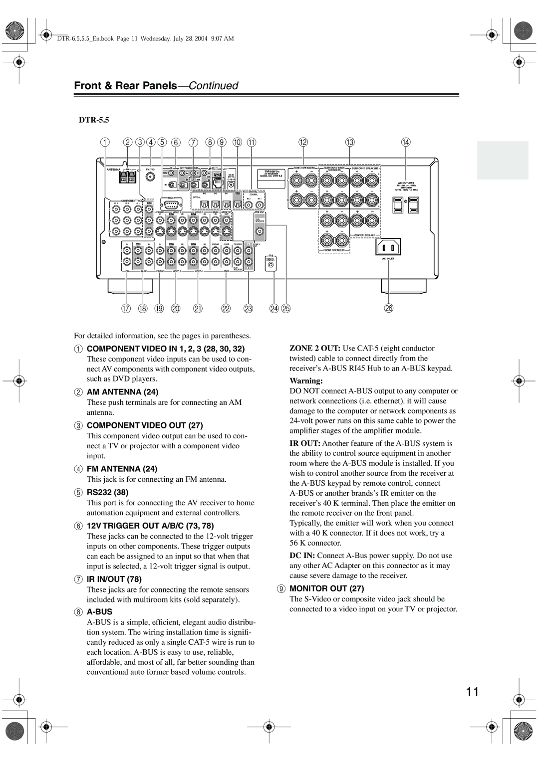
DTR-5.5
Front & Rear Panels
Front Panel
DTR-6.5
Front & Rear Panels
Rear Panel
Display
IR IN/OUT
Component Video in 1, 2, 3 28, 30
RS232
12V Trigger OUT A/B/C 73
Phono in DTR-6.5 only
Optical Digital 27, 28, 30, 32, 34
Coaxial Digital 27, 28, 30, 32, 34
Grounding screw DTR-6.5 only
Using the Remote Controller
Remote Controller
Installing the Batteries
RC-585M
Remote Controller
Receiver Mode
Remote indicator
On button
Remote Mode buttons
Listening mode buttons 58 Surrond button
Standby button
DVD Mode
CD Mode
Pause button
MD/CDR Mode
Play button
Previous & Next / buttons
Reverse Play button
Tape Mode
FR & FF Buttons
Stop button
Enjoying Home Theater
About Home Theater
AV Connection Color Coding
Connecting the AV receiver
About AV Connections
Optical Digital Jacks
Connecting Your Speakers
Connecting the AV receiver
Strip about 5/8 15 mm
Speaker Connection Precautions
Connecting the Speaker Cables
Attach the FM antenna, as shown American Model
Connecting Antenna
Connecting the Indoor FM Antenna
Connecting the AM Loop Antenna
Using a TV/FM Antenna Splitter
Connecting an Outdoor FM Antenna
Connecting an Outdoor AM Antenna
Audio Connection Formats
Connecting Both Audio & Video
Which Connections Should I Use?
Video Connection Formats
Audio Connections
Connecting Your TV or Projector
Monitor Out
DVD player
Connecting a DVD Player
Video Connections
Your TV must also be connected via component video
Using a Multichannel Connection
Connecting a D-VHS VCR for Playback
Connecting a VCR for Playback
TV or VCR, etc
Connecting a VCR for Recording
Playback from the Recording VCR
VCR recording
Satellite, cable, set-top box, LD player, etc
Using Optical or Coaxial Connections
PRSatellite, cable, set-top box, LD player, etc
Camcorder Games console, etc
Connecting a Camcorder, Games Console, etc
Using Analog Connections Using S-Video
CD player
Connecting a CD Player Connecting a Cassette Recorder
Connecting a DAT, CD, or MD Recorder
Analog Connections
Digital source DAT, CD, MD player
Using Optical or Coaxial Connections playback only
Digital Recording
For the DTR-5.5
Connecting a Turntable
For the DTR-6.5
Is for connecting more -compatible components
Connecting a Power Amplifier DTR-6.5 only
Connecting Components
When you start playback on an AV component con
Turning On the AV receiver
Connecting the Power Cords of Other Components
Connecting the Supplied Power Cord
Connecting the RS232 Port
Automatic Speaker Setup
First Time Setup
First Time Setup
Submenus
About the Onscreen Setup Menus
Main menus
Digital Input
Initial Setup
Tor, and then use the Left
Component Video Setup
Main menu appears onscreen
Buttons to select an input selec
Ance Minimum, and then use
Press the Receiver button fol- lowed by the Setup button
Minimum Speaker Impedance not American models
Buttons to select b. Sp Imped
Then use the Left and Right
TV Format Setup not American models
Here you can specify the TV format used in your area
Buttons to select c. TV Format
Buttons to select a. Subwoofer
Speaker Setup
Speaker Setup menu appears
Buttons to select 2. Speaker
Crossover
Tance, and then press Enter
Default
Double Bass
Speaker Distance
Repeat for all speakers
Speaker Distance menu appears
Buttons to specify the dis- tance
Subwoofer 0dB
Speaker Level Calibration
Equalizer Setting
Repeat this step to select TAPE, MD, or CDR
Changing the TAPE/MD/CDR Display
Start playback on the source component
Only the RC-585M remote controller has a Phono button
Basic Operation
Selecting the Input Source
Basic Operation
Setting the Display Brightness
Using the Sleep Timer
Using Headphones
Interpreting Surround Channel Values
Displaying Source Information
You can display various information about the current
Input source as follows
Use the Tuner input selector
Using the Tuner
Tuning into Radio Stations
Listening to the Radio
Displaying Radio Information
Presetting Radio Stations
Selecting Preset Stations
Deleting Presets
THX button DTR-6.5 only
Selecting with the Remote Controller
Selecting on the AV receiver
Surrond button
Multich
About the Listening Modes
Onkyo Original DSP Modes
Advanced Operation
Using the Re-EQ Function
Using the Late Night Function Dolby Digital only
Using the CinemaFILTER DTR-5.5 only
Advanced Operation
Adjusting Individual Speaker Levels
Recording Audio
Recording
Recording Separate AV Sources
AV Recording
Dolby Digital
Advanced Setup
Decoder Setup
Analog/PCM
Multiplex
Advanced Setup
DTS
D.F ch
Settings are explained below
Audio Adjust Functions
Audio Adjust menu appears
PLIIx/Neo6
Mono
Assigning Listening Modes to Input Sources
Theater-Dimensional
Preference menu appears
Setting Preferences
Use the Up and Down Buttons to select the signal for
This section explains the items on the Preference menu
Remote Setup
IntelliVolume
Volume Setup
OSD Setup
Digital Format
Changing the Remote Controller’s ID
6-7., 6-8 V Trigger Setup
Zone
Using Only Speakers in Zone
Using a Receiver/Integrated Amp in Zone
Buttons to select 3. Hardware
Buttons to select a. Powered
Hardware Setup menu appears
Zone 2, and use the Left
Zone 2 OUT L/R jacks can also be used as pre
Outs Hardware Setup menu appears
Using Zone
Using a Multiroom Kit with Zone
Using the Remote Control in Zone
Using the 12V Trigger
Adjusting the Bass & Treble for Zone2
Controlling Out-of-range Components
Using a Multiroom Kit with a Cabinet
Codes for Integra DVD Players
Entering Remote Control Codes
Setting the MD/CDR Button to CDR
Controlling Other Components
Controlling Other Components
Resetting Remote Mode Buttons
Resetting the Remote Controller
SAT satellite receiver
Remote Control Codes
DVD DVD player
ABC
CBL cable receiver
DTR-6.5,5.5En.book Page 84 Wednesday, July 28, 2004 907 AM
DTR-6.5,5.5En.book Page 85 Wednesday, July 28, 2004 907 AM
Controlling a Cable Receiver
Controlling a TV
Buttons
Controlling a VCR Controlling a Satellite Receiver
Rec
Number
Learning Commands from Another Remote Controller
Running Macros
Using Macros
Making Macros
Troubleshooting
Troubleshooting
Zone 2 has turned off?
Remote controller doesn’t work?
Can’t control other components?
Can’t record?
Display doesn’t work?
Sound changes when I connect my head- phones?
Speaker volume cannot be set as required?
Speaker distance cannot be set as required?
Video Section
Specifications DTR-6.5
Amplifier Section
General
Specifications DTR-5.5
3 4 3 8 2