DTR-7.8
Avis
Important Safety Instructions
Power
Precautions
For models having a power cord with a polarized plug
FCC Information for User
For British models
Precautions
Contents
Features
Make sure you have the following accessories
Supplied Accessories
THX Ultra2
Speaker cable labels
Zone 2 Room Zone 3 Room
Multiroom Capability
Main Room
Front Panel
Getting to Know the AV Receiver
Getting to Know the AV Receiver
Display
Rear Panel
Digital Coaxial in 1, 2,
IR in A/B and OUT
Digital Optical in 1, 2, and OUT
GND screw
Using the Remote Controller
Remote Controller
Installing the Batteries
Receiver/Tape Mode
Remote Controller
About the Remote Controller Modes
Remote Mode buttons
Listening Mode buttons
Tape mode
Standby button
DVD Mode
CD/MD/CDR Modes
Arrow / and Enter buttons
Dock Mode
Album +/- button
Previous button
Enjoying Home Theater
Connecting Your Speakers
Subwoofer
Surround back left and right speakers
Connecting Your Speakers
Connecting Your Speakers
Connecting the Speaker Cables
Speaker Connection Precautions
Fully insert the bare wire
Strip about 5/8
Bi-amping Speaker Hookup
Bi-amping the Front Speakers
Connecting the Indoor FM Antenna
Connecting Antennas
Connecting the AM Loop Antenna
Attach the FM antenna, as shown American Model
Connecting an Outdoor FM Antenna
Connecting Antennas
Connecting an Outdoor AM Antenna
Using a TV/FM Antenna Splitter
About AV Connections
Connecting Your Components
Optical Digital Jacks
AV Connection Color Coding
Connecting Audio and Video Signals to the AV Receiver
Connecting Your Components
Hdmi Monitor Setting Set to Yes
Which Connections Should I Use?
Audio Signal Flow Chart DVD player, etc
Hdmi Monitor Setting Set to No
Audio Connection Formats
Ponent Video Monitor OUT 2/ZONE 2 OUT to your TV
Video Connection
Connecting a TV or Projector
Audio Connection
Hint
Connecting a DVD player
DVD player
Hooking Up the Multichannel Input
VCR or DVR
Connecting a VCR or DVR for Playback
Digital Optical OUT
Connecting a VCR or DVR for Recording
Satellite, cable, set-top box, etc
About Hdmi
Connecting Components with Hdmi
Supported Audio Formats
About Copyright Protection
Making Hdmi Connections
Video Signals
Audio Signals
Game Console
Connecting a Game Console
Camcorder, etc
Connecting a Camcorder or Other AV Component
Connecting a Turntable
Connecting a CD Player
Step
CD player
Power amplifier
Connecting a Cassette, CDR, MiniDisc, or DAT Recorder
Connecting a Power Amplifier
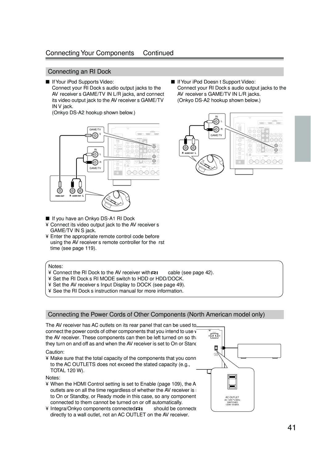
If you have an Onkyo DS-A1 RI Dock
Connecting an RI Dock
Connecting the Power Cord
Connecting Integra/Onkyo Components
Auto Power On/Standby
Remote Control
Turning On the AV Receiver
Do the automatic speaker setup-this is essential
Turning On and Standby
Up and Running in a Few Easy Steps
Speaker Settings
First Time Setup
Hdmi Monitor Setup
First Time Setup
Assign, and then press Enter
Use the Up and Down Buttons to select 1. Monitor
Use the Left and Right / buttons to select
Buttons to select Monitor Out2
Tor, and use the Left and Right
Buttons to select 1. Input/Output
Buttons to select an input selec
Video Input, and then press Enter
Component Video Input Setup
Use the Up and Down Buttons to select 3. Component
Press the Tape or Game/TV
Changing the Input Display
Input selector button so that
Tape or GAME/TV appears
These are the default assignments
Digital Input Setup
Digital Input menu appears
Input selector Audio input
Setup
Analog Input menu appears
Analog Input Setup
Tor
You can assign the multichannel input
Using Audyssey MultEQ XT
Automatic Speaker Setup Audyssey MultEQ XT
Measurement Positions
1st measurement position
When prompted, place the setup
Place the setup microphone at
Turn on the AV receiver and the connected TV
Press Enter
When the calculations are com
Error Messages
Disconnect the setup micro Phone
Plete, the following screen
Writing Error
Speaker Detect Error
One of the front speakers has not been detected
One of the surround speakers has not been detected
Using a Powered Subwoofer
Changing the Speaker Settings Manually
Reviewing the Results
You want to review, and then
Buttons to select 6. Miscella
TV Format Setup Not North American models
Neous, and then press Enter
Buttons to select TV Format
Hardware Setup menu appears
AM Frequency Step Setup on some models
Buttons to select 7. Hardware
Buttons to select AM Freq
Playing Your AV Components
Select a listening mode and enjoy
Basic AV Receiver Operation
Start playback on the source component
Listening to the Radio
Tuning into AM/FM Radio Stations
Listening to AM/FM Stations
Use the Tuner input selector button to select AM or FM
Listening to the Radio
Tuning into Stations by Frequency
Displaying AM/FM Radio Information
Lowed by the D.TUN button
What is RDS?
Using RDS not North American model
RDS Program Types PTY
This allows you to search RDS radio stations by type see
Listening to Traffic News TP
Displaying Radio Text RT
Finding Stations by Type PTY
Setting the Satellite Radio Mode
Connecting the XM Mini-Tuner and Home Dock
Mode button, followed by
Listening to XM Satellite Radio North American Model Only
Use the Tuning Up and Down
When you’ve finished, press the Setup button
Selecting XM Satellite Radio
Signing Up for XM Satellite Radio
Selecting XM Radio Channels
Channel Search Mode Direct Tuning
To sign up, go to
Buttons to select a channel in that category
Positioning the XM Mini-Tuner System
Displaying XM Radio Information
XM Radio Messages
What is Sirius Satellite Radio?
Setting Up the SiriusConnect Home Tuner
Positioning the Antenna
Important Sirius Satellite Radio Information
Selecting Sirius Satellite Radio
Selecting Sirius Satellite Radio Channels
Signing Up for Sirius Satellite Radio
Parental Lock
Changing the PIN Number
Use the Up and Down Buttons to select 5. Sirius
Use the Up and Down Buttons to select Edit Code
Parental Lock, and then press
Press the D.TUN button,
Positioning the SiriusConnect Home Antenna
Tuner button, and Setup but
Displaying Sirius Satellite Radio Information
Buttons to select 4. Satellite Radio, and then press Enter
Position the SiriusConnect Home
Sirius Satellite signal strength
Sirius Satellite Radio Messages
Deleting Presets
Presetting AM, FM, XM, and Sirius Stations
Selecting Presets
Setting the Display Brightness
Adjusting Speaker Levels
Common Functions
Muting the AV Receiver
Using Headphones
Using the Sleep Timer
Common Functions
Displaying Source Information
Selecting Audio Inputs Specifying the Digital Signal Format
Selecting with the Remote Controller
Using the Listening Modes
Selecting the Listening Modes
Selecting on the AV Receiver
Analog and PCM Sources
Using the Listening Modes
Listening Modes Available for Each Source Format
Sacd
DSD, Dolby Digital, and Dolby Digital Plus Sources
DTS-ES
TrueHD and DTS Sources
DTS-HD Sources
Sound is output by the front left and right speakers
Use this mode with any stereo movie e.g., TV, DVD, VHS
About the Listening Modes
Onkyo Original DSP Modes
Recording from Different AV Sources
Recording
Recording the Input Source
Menu Map
Onscreen Setup Menus
Main menu
Submenu
Using the Re-EQ Function
Adjusting the Listening Modes
Using the Late Night Function
Night button repeatedly
Tone Control Settings
Adjusting the Listening Modes
Audio Adjust
PLIIx/Neo6 Settings
Direct Setting
Multiplex/Mono Settings
Dolby Digital Settings
Listening Mode Presets
Theater-Dimensional Setting
LFE Level Settings
Buttons to select an audio for
Tening mode
Mat, and use the Left and Right
Buttons to select a lis
Speaker Setup
Advanced Setup
Speaker Settings
Buttons to select Subwoofer
Fixed at Full Band if Subwoofer is set to No
Advanced Setup
Double Bass
Low-Pass Filter for the LFE Channel
Surr Back R and Surr Back L
Speaker Distance
Distances cannot be set if Speaker
Speaker Distance screen appears
Speaker Level Calibration
100
101
Equalizer Settings
THX Audio Setup screen appears
THX Audio Setup
102
Repeat steps 6 and 7 for each speaker
103
Source Setup
104
IntelliVolume
Name Edit
Sync
Satellite Radio
105
Sirius Parental Lock
To correct a character
Volume Setup
Miscellaneous Setup
Volume Display
Maximum Volume
107
OSD Setup
12V Trigger A/B/C Setup
Remote Control
Hardware Setup
108
Zone 2 and Zone
Analog Multich
109
110
Lock Setup
Network
Lock
Connecting Your Zone 2 Speakers Directly to the AV receiver
Connecting Zone
Connecting Your Zone 2 Speakers to an Amp in Zone
Zone 2 and Zone
112
Connecting Your Zone 3 Speakers
Zone 2 and Zone
Zone 2 Video Outputs
Buttons to select Powered
Powered Zone 2 Setting
113
Zone 2, and use the Left
Using Zone 2 and Zone
Zone 2/Zone 3 Out Settings
114
Right / buttons to
Turning Off Zones
115
Selecting an Input Source for Zones
Adjusting the Balance of Zones
Adjusting the Volume of Zones Muting Zones
Adjusting the Tone of Zone
116
117
Using the 12V Triggers
Left and Right But
Tons to select 0 sec, 1 sec, 2 sec, or 3 sec
Using a Multiroom Kit with Zone 2/3
Using a Multiroom Kit with a Cabinet
Using a Multiroom Kit with Other Components
Connecting block
119
Entering Remote Control Codes
Controlling Other Components
Resetting the Remote Mode Buttons
Resetting the Remote Controller
120
Controlling Other Components
121
122
Learning Commands
123
Using Macros
Making Macros
Running Macros
124
Troubleshooting
125
Troubleshooting
126
127
Specifications
3 4 4 4 5 9 a