C H A P T E R 3 Configure the module and connect the cables
Cabling to a Matrix | To accomplish successful link aggregation, the modules must be in- | |
Module | stalled on the same side of separate switches (for example, both mod- | |
| ules in Slot A). |
|
| Note The | |
| 1000Base Modules must be connected to ports 2 and 3 on | |
| the Matrix Module for link aggregation to work. | |
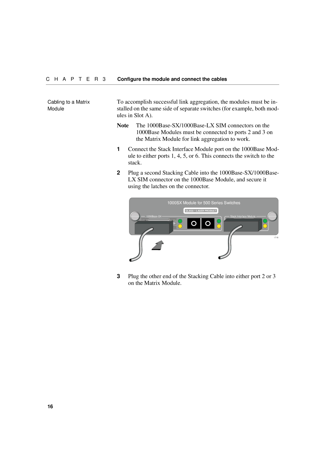
| 1 Connect the Stack Interface Module port on the 1000Base Mod- | |
| ule to either ports 1, 4, 5, or 6. This connects the switch to the | |
| stack. |
|
| 2 Plug a second Stacking Cable into the | |
| LX SIM connector on the 1000Base Module, and secure it | |
| using the latches on the connector. | |
|
| 1000SX Module for 500 Series Switches |
|
| CLASS 1 LASER PRODUCT |
| Stack Interface Module | |
|
| 1718 |
3Plug the other end of the Stacking Cable into either port 2 or 3 on the Matrix Module.
16