A P P E N D I X B | Intel Express 100BASE- TX Stackable Hub |
NOTE
Media Independent Interface (MII) cables for
2.Add the LSDVs for all the segments in the path.
3.Determine the delay for each repeater in the path.
Repeater delay values are specified in bit times. The default maximum repeater delay value for a Class 1 repeater is 140 bit times. There is a one repeater maximum for networks using Class I repeaters.
4.Determine the DTE delay values for the path.
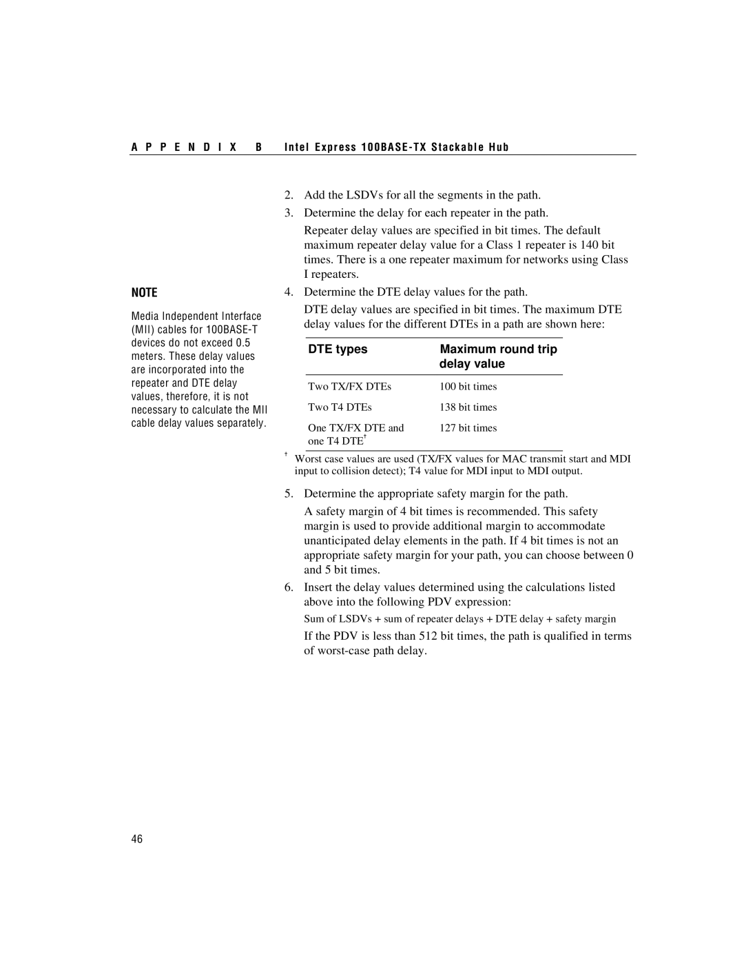
DTE delay values are specified in bit times. The maximum DTE delay values for the different DTEs in a path are shown here:
DTE types | Maximum round trip |
| delay value |
|
|
Two TX/FX DTEs | 100 bit times |
Two T4 DTEs | 138 bit times |
One TX/FX DTE and | 127 bit times |
one T4 DTE✝ |
|
✝Worst case values are used (TX/FX values for MAC transmit start and MDI input to collision detect); T4 value for MDI input to MDI output.
5.Determine the appropriate safety margin for the path.
A safety margin of 4 bit times is recommended. This safety margin is used to provide additional margin to accommodate unanticipated delay elements in the path. If 4 bit times is not an appropriate safety margin for your path, you can choose between 0 and 5 bit times.
6.Insert the delay values determined using the calculations listed above into the following PDV expression:
Sum of LSDVs + sum of repeater delays + DTE delay + safety margin
If the PDV is less than 512 bit times, the path is qualified in terms of
46