A P P E N D I X B |
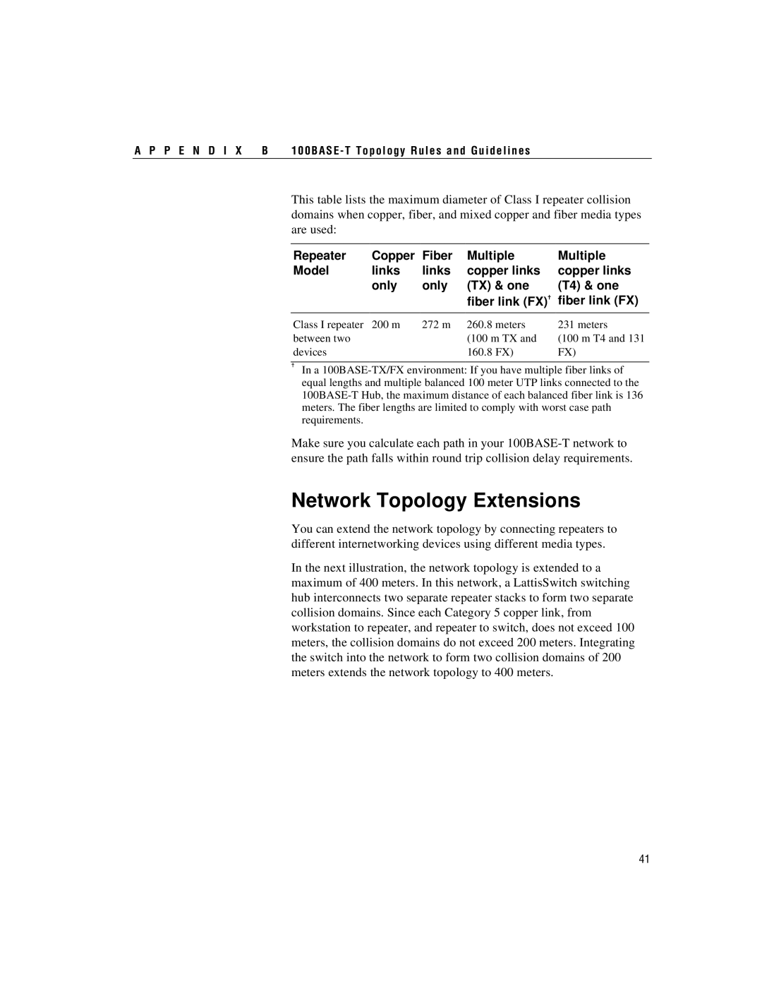
This table lists the maximum diameter of Class I repeater collision domains when copper, fiber, and mixed copper and fiber media types are used:
Repeater | Copper | Fiber | Multiple | Multiple |
Model | links | links | copper links | copper links |
| only | only | (TX) & one | (T4) & one |
|
|
| fiber link (FX)✝ | fiber link (FX) |
|
|
|
|
|
Class I repeater | 200 m | 272 m | 260.8 meters | 231 meters |
between two |
|
| (100 m TX and | (100 m T4 and 131 |
devices |
|
| 160.8 FX) | FX) |
✝In a
Make sure you calculate each path in your
Network Topology Extensions
You can extend the network topology by connecting repeaters to different internetworking devices using different media types.
In the next illustration, the network topology is extended to a maximum of 400 meters. In this network, a LattisSwitch switching hub interconnects two separate repeater stacks to form two separate collision domains. Since each Category 5 copper link, from workstation to repeater, and repeater to switch, does not exceed 100 meters, the collision domains do not exceed 200 meters. Integrating the switch into the network to form two collision domains of 200 meters extends the network topology to 400 meters.
41