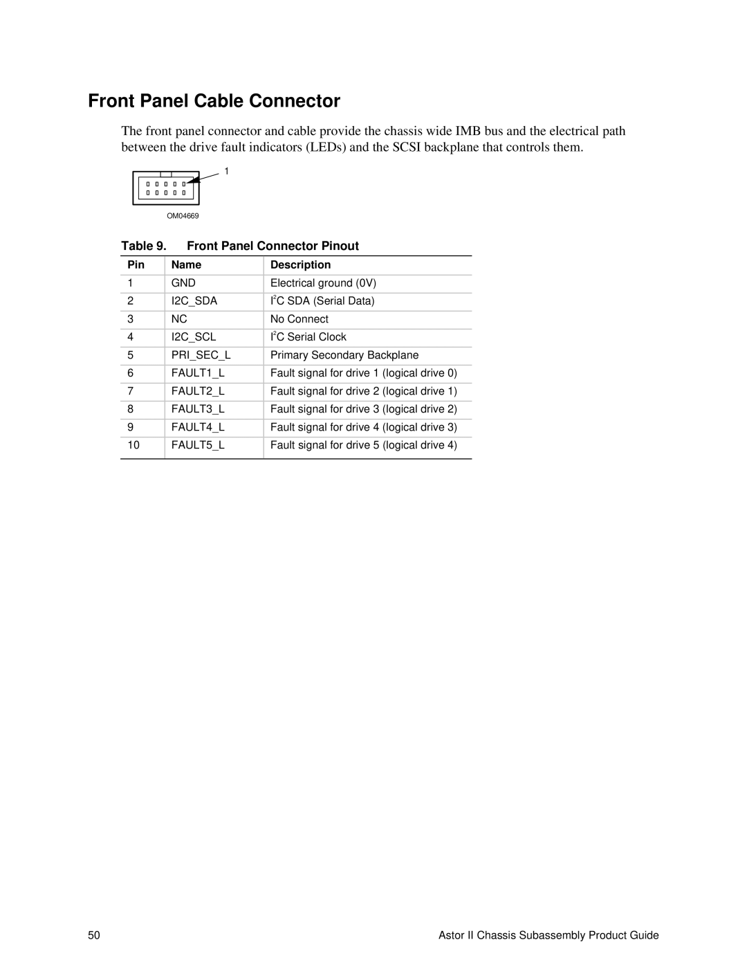
Front Panel Cable Connector
The front panel connector and cable provide the chassis wide IMB bus and the electrical path between the drive fault indicators (LEDs) and the SCSI backplane that controls them.
|
|
|
|
|
|
| 1 |
| |
|
|
|
|
|
|
|
|
| |
|
|
|
|
|
|
|
|
|
|
|
|
|
|
|
|
|
| ||
|
|
|
|
| OM04669 |
| |||
Table 9. |
| Front Panel Connector Pinout | |||||||
|
|
|
|
| |||||
Pin |
|
| Name | Description | |||||
|
|
|
|
|
|
|
| ||
1 |
|
|
|
|
| GND | Electrical ground (0V) | ||
|
|
|
|
|
|
|
| ||
2 |
|
|
|
|
| I2C_SDA | I2C SDA (Serial Data) | ||
|
|
|
|
|
|
|
| ||
3 |
|
|
|
|
| NC | No Connect | ||
|
|
|
|
|
|
|
| ||
4 |
|
|
|
|
| I2C_SCL | I2C Serial Clock | ||
|
|
|
|
|
|
|
| ||
5 |
|
|
|
|
| PRI_SEC_L | Primary Secondary Backplane | ||
|
|
|
|
|
|
|
| ||
6 |
|
|
|
|
| FAULT1_L | Fault signal for drive 1 (logical drive 0) | ||
|
|
|
|
|
|
|
| ||
7 |
|
|
|
|
| FAULT2_L | Fault signal for drive 2 (logical drive 1) | ||
|
|
|
|
|
|
|
| ||
8 |
|
|
|
|
| FAULT3_L | Fault signal for drive 3 (logical drive 2) | ||
|
|
|
|
|
|
|
| ||
9 |
|
|
|
|
| FAULT4_L | Fault signal for drive 4 (logical drive 3) | ||
|
|
|
|
|
| ||||
10 |
|
|
| FAULT5_L | Fault signal for drive 5 (logical drive 4) | ||||
|
|
|
|
|
|
|
|
|
|
50 | Astor II Chassis Subassembly Product Guide |
