PX875P PRO/ PX875P
Audio Connectors
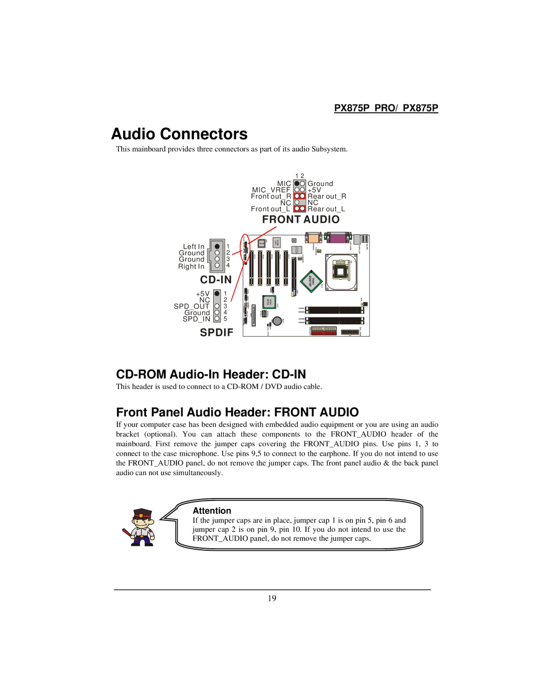
This mainboard provides three connectors as part of its audio Subsystem.
1 2
MIC ![]() MIC_VREF
MIC_VREF ![]()
![]() Front out_R
Front out_R ![]()
NC ![]()
![]()
![]() Front out_L
Front out_L ![]()
Ground +5V Rear out_R NC
Rear out_L
FRONT AUDIO
Left In | 1 |
Ground | 2 |
Ground | 3 |
Right In | 4 |
+5V | 1 |
NC | 2 |
SPD_OUT | 3 |
Ground | 4 |
SPD_IN | 5 |
SPDIF
FR O NT | 21 |
AU DIO CD | 1 |
1 | |
SPDIF | PCI5 |
| 21 |
|
| U SB2 | |
| 21 |
|
| USB 3 | |
SPEAKER | 910 | CHASFAN |
1 | ||
| 1 |
|
1 | PWRLE D2 1 | FDC |
SW/LED | 10 |
|
| 9 |
|
BIOS | U21 |
|
| 3COM LAN |
| W83627HF ALC 650 | Winbond |
| SOUND | CPUFA | 1 |
| PRT/COM | USB/LAN | KB/MS |
PCI4 |
| PCI3 | PCI2 | PCI1 |
| 1 | AUXFAN |
| N |
| Socket 478 | U 8 |
|
| |
|
| U | 1 | 2 |
|
|
| 82875P | Intel |
|
| U12 |
|
|
|
|
| SB4 | 910 |
|
| AGP |
|
|
|
|
|
|
|
| |
| In tel IC H 5 | U 19 |
|
| DIM M1 |
|
|
|
|
| ATX 1 2V |
| |||
SATA1 | SATA2 |
|
|
|
|
|
|
|
|
|
|
|
| ||
|
|
|
|
| DIM M2 |
|
|
|
|
|
|
| |||
|
|
|
|
| BAT1 |
| DIM M3 |
|
|
|
|
|
|
| |
| 1 | 1 |
|
|
| DIM M4 |
|
|
|
|
|
|
| ||
| JP1 CAS E O P E N |
|
|
|
|
| IDE2 ID E1 |
|
|
|
|
| ATX PWR |
| |
CD-ROM Audio-In Header: CD-IN
This header is used to connect to a
Front Panel Audio Header: FRONT AUDIO
If your computer case has been designed with embedded audio equipment or you are using an audio bracket (optional). You can attach these components to the FRONT_AUDIO header of the mainboard. First remove the jumper caps covering the FRONT_AUDIO pins. Use pins 1, 3 to connect to the case microphone. Use pins 9,5 to connect to the earphone. If you do not intend to use the FRONT_AUDIO panel, do not remove the jumper caps. The front panel audio & the back panel audio can not use simultaneously.
Attention
If the jumper caps are in place, jumper cap 1 is on pin 5, pin 6 and jumper cap 2 is on pin 9, pin 10. If you do not intend to use the FRONT_AUDIO panel, do not remove the jumper caps.
19
