1 HARDWARE INSTALLATION
Using the included RJ45 Ethernet cable (and more, as needed), make your
1.Turn off all devices to be incorporated into the network, including any PCs, switches/hubs, the modem and the router.
2.Connect the LAN or Ethernet network port of the cable/DSL modem to the router’s WAN port.
3.Connect PCs (and any switch/hub used to expand the network) to the router’s LAN ports.
4.Turn on the cable/DSL modem.
5.Use the included power adapter to connect the router to an AC outlet.
6.Turn on the PC you’ll be using to configure the router.
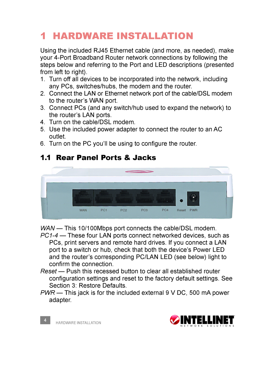
1.1 Rear Panel Ports & Jacks
WAN | PC1 | PC2 | PC3 | PC4 | Reset PWR |
WAN — This 10/100Mbps port connects the cable/DSL modem.
PCs, print servers and remote hard drives. If you connect a LAN port to a switch or hub, check that both the device’s Power LED and the router’s corresponding PC/LAN LED (see below) light to confirm the connection.
Reset — Push this recessed button to clear all established router configuration settings and reset to the factory default settings. See Section 3: Restore Defaults.
PWR — This jack is for the included external 9 V DC, 500 mA power adapter.
4HARDWARE INSTALLATION