SECTION 8—TOP SHROUD AND WHEELS
Replacing Front/Rear Caster Assemblies
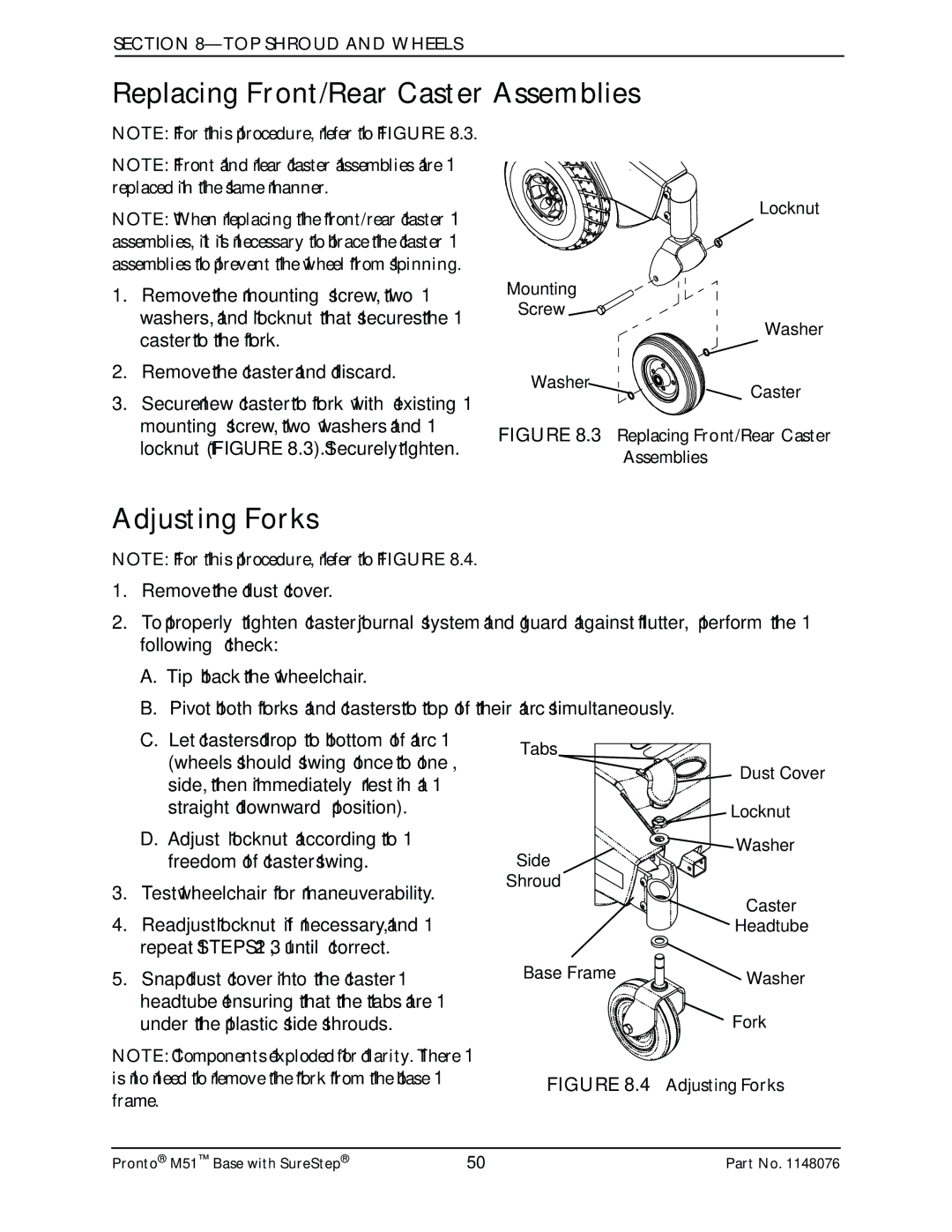
NOTE: For this procedure, refer to FIGURE 8.3.
NOTE: Front and rear caster assemblies are replaced in the same manner.
NOTE: When replacing the front/rear caster assemblies, it is necessary to brace the caster assemblies to prevent the wheel from spinning.
1.Remove the mounting screw, two washers, and locknut that secures the caster to the fork.
2.Remove the caster and discard.
3.Secure new caster to fork with existing mounting screw, two washers and locknut (FIGURE 8.3). Securely tighten.
Adjusting Forks
NOTE: For this procedure, refer to FIGURE 8.4.
1.Remove the dust cover.
2.To properly tighten caster journal system and guard against flutter, perform the following check:
A.Tip back the wheelchair.
B.Pivot both forks and casters to top of their arc simultaneously.
C.Let casters drop to bottom of arc (wheels should swing once to one‐ side, then immediately rest in a straight downward position).
D.Adjust locknut according to freedom of caster swing.
3.Test wheelchair for maneuverability.
4.Readjust locknut if necessary, and repeat STEPS 2‐3 until correct.
5.Snap dust cover into the caster headtube ensuring that the tabs are under the plastic side shrouds.
NOTE: Components exploded for clarity. There is no need to remove the fork from the base frame.
Tabs
| Dust Cover |
| Locknut |
Side | Washer |
| |
Shroud |
|
| Caster |
| Headtube |
Base Frame | Washer |
| |
| Fork |
FIGURE 8.4 Adjusting Forks
Pronto® M51™ Base with SureStep® | 50 | Part No. 1148076 |