F
W D
W H E E L C H A I R S
PROCEDURE 10 | FWD WHEELCHAIRS | ||
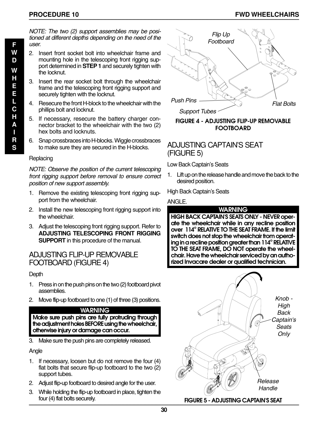
NOTE: The two (2) support assemblies may be posi- | Flip Up |
| |
tioned at different depths depending on the need of the |
| ||
Footboard |
| ||
user. |
| ||
|
| ||
2. Insert front socket bolt into wheelchair frame and |
|
| |
mounting hole in the telescoping front rigging sup- |
|
| |
port determined in STEP 1 and securely tighten with |
|
| |
the locknut. |
|
| |
3. Insert the rear socket bolt through the wheelchair |
|
| |
frame and the telescoping front rigging support and |
|
| |
securely tighten with the locknut. | Push Pins |
| |
4. Resecure the front | Flat Bolts | ||
| |||
phillips bolt and locknut. | Support Tubes |
| |
5. If necessary, resecure the battery charger con- | FIGURE 4 - ADJUSTING | ||
nector bracket to the wheelchair with the two (2) | |||
FOOTBOARD |
| ||
hex bolts and locknuts. |
| ||
|
| ||
6. Snap crossbraces into | ADJUSTING CAPTAIN'S SEAT |
| |
to make sure they are secured in the |
| ||
Replacing | (FIGURE 5) |
| |
Low Back Captain's Seats |
| ||
NOTE: Observe the position of the current telescoping |
| ||
1. Lift up on the release handle and move the back to the | |||
front rigging support before removal to ensure correct | |||
position of new support assembly. | desired position. |
| |
|
| ||
1. Remove the existing telescoping front rigging sup- | High Back Captain's Seats |
| |
port from the wheelchair. | ANGLE. |
| |
2. Install the new telescoping front rigging support into | WARNING |
| |
the wheelchair. | HIGH BACK CAPTAIN'S SEATS ONLY - NEVER oper- | ||
3. Adjust the telescoping front rigging support. Refer to | ate the wheelchair while in any recline position | ||
over 114o RELATIVE TO THE SEAT FRAME. If the limit | |||
ADJUSTING TELESCOPING FRONT RIGGING | switch does not stop the wheelchair from operat- | ||
SUPPORT in this procedure of the manual. | |||
ing in a recline position greater than 114o RELATIVE | |||
ADJUSTING | TO THE SEAT FRAME, DO NOT operate the wheel- | ||
chair. Have the wheelchair serviced by an autho- | |||
FOOTBOARD (FIGURE 4) | rized Invacare dealer or qualified technician. | ||
Depth |
|
| |
1.Press in on the push pins on the two (2) footboard pivot assemblies.
2. Move | Knob - | |
WARNING | High | |
Back | ||
Make sure push pins are fully protruding through | ||
Captain's | ||
theadjustmentholesBEFOREusingthewheelchair, | ||
Seats | ||
otherwise injury or damage can occur. | ||
Only | ||
|
3. Make sure the push pins are completely released.
Angle
1. If necessary, loosen but do not remove the four (4) flat bolts that secure
2. | Adjust | Release | |
Handle | |||
3. | While holding the | ||
| |||
| four (4) flat bolts securely. | FIGURE 5 - ADJUSTING CAPTAIN'S SEAT | |
|
| 30 |