PROCEDURE 11 | RWD WHEELCHAIRS |
Installing/Adjusting Wheel Locks (FIGURE 9) | INSTALLING/REMOVING ANTI- |
NOTE: Before adjusting or replacing the wheel lock as- | TIPPERS (FIGURE 10) |
semblies, ensure that the tires are inflated to the recom- | Installing |
mended psi on the side wall of tire. |
|
R W D
1.Position the wheel lock on the wheelchair frame.
2.Loosely install the hex screw that secures the wheel lock to the wheelchair frame.
3.Make sure wheel lock is disengaged from rear wheel.
4.Measure the distance between the WHEEL LOCK SHOE and the REAR WHEEL.
5.Slide the wheel lock along the wheelchair until the mea- surement is between 5/32 and
6.Tighten the wheel lock to the wheelchair frame.
7.Repeat this procedure for the opposite wheel lock.
8.Disengage the clutches. Refer to ENGAGING/DISEN- GAGING CLUTCHES in this procedure of the manual.
9.Engage the wheel locks and push against the wheel- chair to determine if the wheel locks engage the rear wheels enough to hold the wheelchair.
10.Repeat STEPS
11.Engage clutches. Refer to ENGAGING/DISENGAG- ING CLUTCHES in this procedure of the manual.
Wheelchair Frame
Hex Screw
Wheel Lock
Shoe
Rear Wheel | 5/32 to |
FIGURE 9 - INSTALLING/ADJUSTING WHEEL LOCKS
WARNING
1.Press release buttons IN and insert the
2.Measure the distance between the bottom of the anti- tipper wheels and the ground/floor.
NOTE: A
3.If the distance between the bottom of the
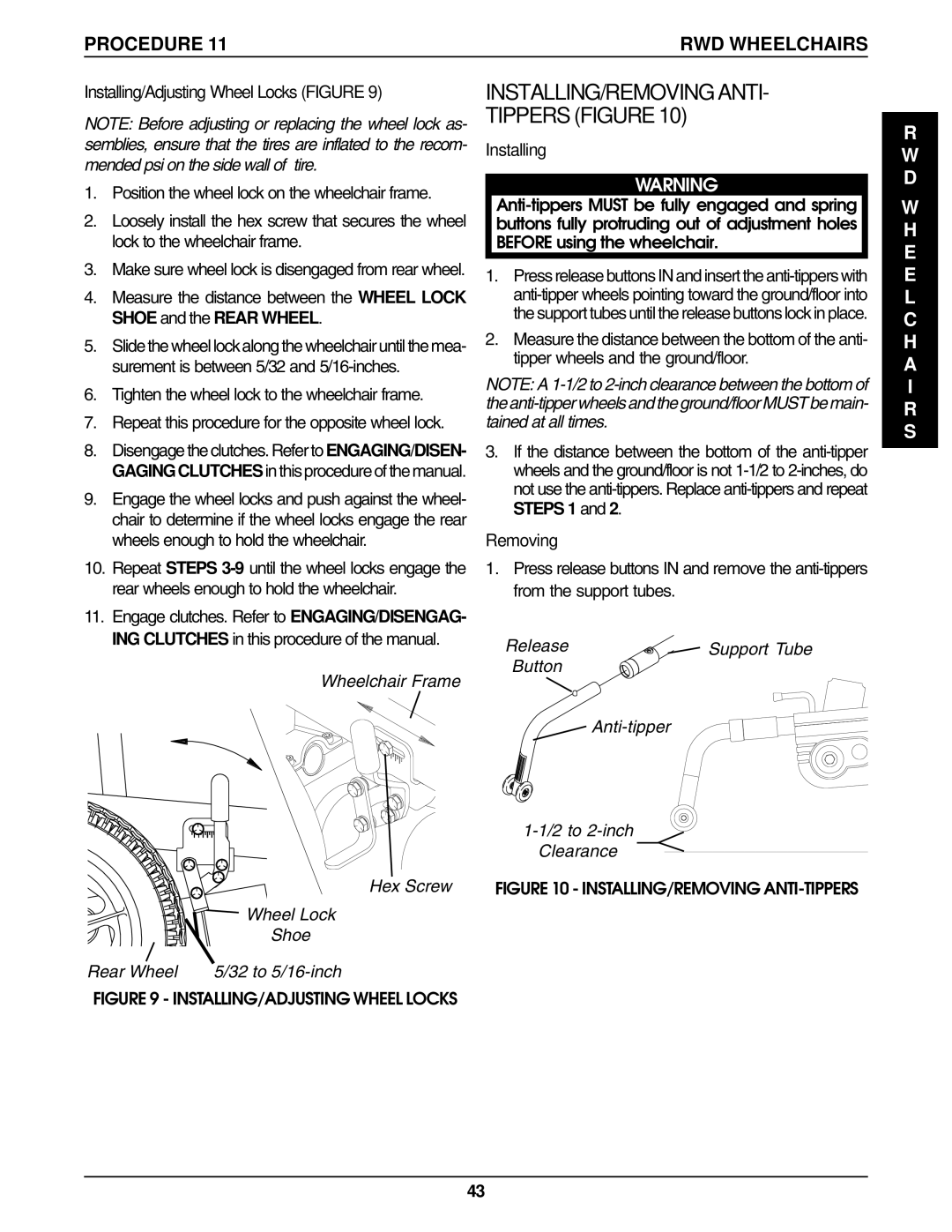
Removing
1.Press release buttons IN and remove the
Release | Support Tube |
Button |
|
|
Clearance
FIGURE 10 - INSTALLING/REMOVING ANTI-TIPPERS
W H E E L C H A I R S
43