RWD WHEELCHAIRS | PROCEDURE 11 |
R
W
D
W
H
E
E
L
C H A I R S
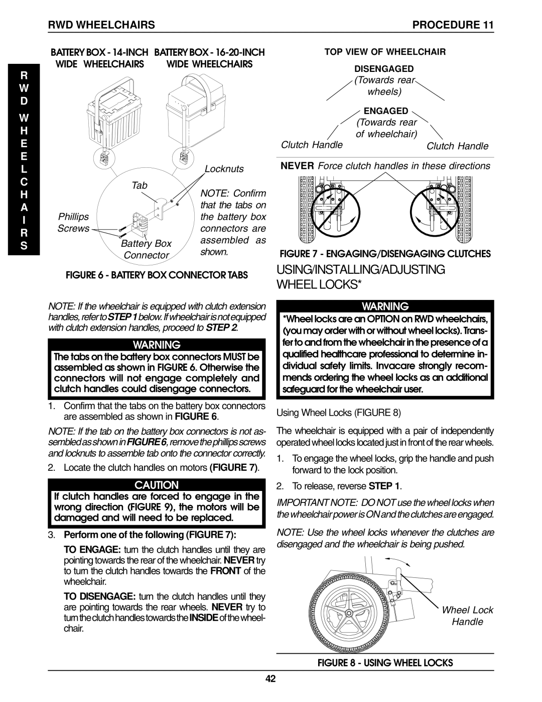
BATTERY BOX -
WIDE WHEELCHAIRS | WIDE WHEELCHAIRS |
|
| Locknuts |
| Tab | NOTE: Confirm |
|
| |
|
| that the tabs on |
Phillips |
| the battery box |
Screws |
| connectors are |
| Battery Box | assembled as |
| shown. | |
| Connector | |
|
|
FIGURE 6 - BATTERY BOX CONNECTOR TABS
NOTE: If the wheelchair is equipped with clutch extension handles,refertoSTEP1below.Ifwheelchairisnotequipped with clutch extension handles, proceed to STEP 2.
WARNING
The tabs on the battery box connectors MUST be assembled as shown in FIGURE 6. Otherwise the connectors will not engage completely and clutch handles could disengage connectors.
1.Confirm that the tabs on the battery box connectors are assembled as shown in FIGURE 6.
NOTE: If the tab on the battery box connectors is not as- sembledasshowninFIGURE6,removethephillipsscrews and locknuts to assemble tab onto the connector correctly.
2. Locate the clutch handles on motors (FIGURE 7).
CAUTION
If clutch handles are forced to engage in the wrong direction (FIGURE 9), the motors will be damaged and will need to be replaced.
3.Perform one of the following (FIGURE 7):
TO ENGAGE: turn the clutch handles until they are pointing towards the rear of the wheelchair. NEVER try to turn the clutch handles towards the FRONT of the wheelchair.
TO DISENGAGE: turn the clutch handles until they are pointing towards the rear wheels. NEVER try to turntheclutchhandlestowardstheINSIDEofthewheel- chair.
TOP VIEW OF WHEELCHAIR
| DISENGAGED |
| (Towards rear |
| wheels) |
| ENGAGED |
| (Towards rear |
Clutch Handle | of wheelchair) |
Clutch Handle |
NEVER Force clutch handles in these directions
FIGURE 7 - ENGAGING/DISENGAGING CLUTCHES
USING/INSTALLING/ADJUSTING WHEEL LOCKS*
WARNING
*Wheel locks are an OPTION on RWD wheelchairs, (you may order with or without wheel locks). Trans- fer to and from the wheelchair in the presence of a qualified healthcare professional to determine in- dividual safety limits. Invacare strongly recom- mends ordering the wheel locks as an additional safeguard for the wheelchair user.
Using Wheel Locks (FIGURE 8)
The wheelchair is equipped with a pair of independently operated wheel locks located just in front of the rear wheels.
1.To engage the wheel locks, grip the handle and push forward to the lock position.
2.To release, reverse STEP 1.
IMPORTANT NOTE: DO NOT use the wheel locks when the wheelchair power is ON and the clutches are engaged.
NOTE: Use the wheel locks whenever the clutches are disengaged and the wheelchair is being pushed.
Wheel Lock
Handle
FIGURE 8 - USING WHEEL LOCKS
42