FWD WHEELCHAIRS | PROCEDURE 10 |
Installing Side Shrouds and Fillers
1.Position the side shroud and filler on the wheelchair frame.
2.Line up the mounting holes in the side shroud and filler with the mounting holes in the wheelchair frame.
CAUTION
DO NOT overtighten the phillips screws and phil- lips bolt that secure the side shroud to the wheel- chair frame - otherwise damage to the side shroud can occur.
3. | Install the phillips screws, bolts, washers and lock- |
| nuts that secure the side shroud and filler to the wheel- |
| chair frame and tighten securely. DO NOT OVER- |
| TIGHTEN. Refer to FIGURE 8 for phillips screw, bolt, |
| washer and locknut locations. |
4. | Repeat STEPS |
| chair, if necessary. |
5. | Perform one (1) of the following: |
| A. INTEGRATED SLING SEAT MODELS - Unfold |
| the wheelchair. Refer to TRANSPORTING EX- |
| CEL in this procedure of the manual. |
| B. CAPTAIN'S SEAT MODELS- Reinstall the |
E.Tuck the excess battery charger cable into the spiral wire cover on the wiring harness.
Battery Charger Connector Cable too Short -
A.Pull the battery charger cable out of the spiral wire cover on the wiring harness.
B.Reposition the battery charger connector bracket on the opposite side of the wheelchair frame.
C.Line up the mounting holes in the battery charger connector bracket and the wheelchair frame.
D.Install the hex bolt through the wheelchair frame and battery charger bracket.
E.Install the locknut onto the hex bolt and tighten securely.
5.If necessary, install the battery charger cover on the opposite filler shroud.
6.Unfold the wheelchair. Refer to TRANSPORTING EXCEL in this procedure of the manual.
Spiral Wire | Hex Bolt | |
Cover | ||
|
Wheelchair
F
W D
W H E E L C H A I R S
Captain's Seat onto the wheelchair. Refer to RE- |
MOVING/INSTALLING CAPTAIN'S SEATin this |
procedure of the manual. |
6. Reinstall the rear shroud onto the wheelchair. Refer |
Battery Charger
Cable
Frame
to REMOVING/INSTALLING REAR SHROUD in this |
procedure of the manual. |
7. Reinstall the front shroud onto the wheelchair. Refer |
to REMOVING/INSTALLING FRONT SHROUD in |
this procedure of the manual. |
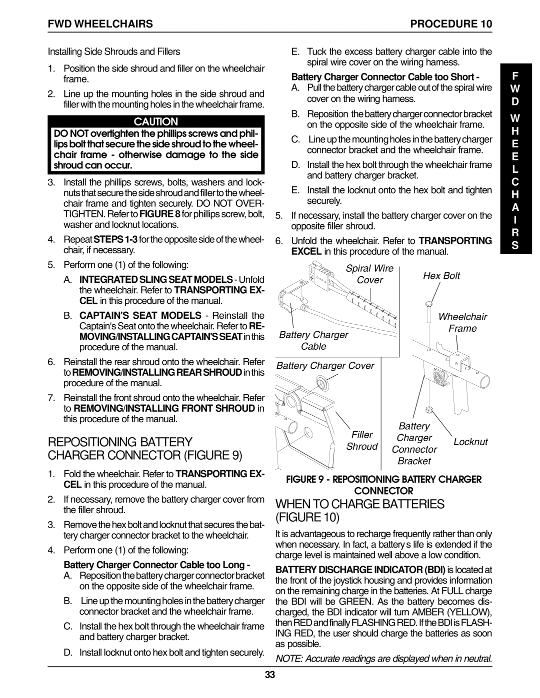
REPOSITIONING BATTERY CHARGER CONNECTOR (FIGURE 9)
1.Fold the wheelchair. Refer to TRANSPORTING EX- CEL in this procedure of the manual.
2.If necessary, remove the battery charger cover from the filler shroud.
3.Remove the hex bolt and locknut that secures the bat- tery charger connector bracket to the wheelchair.
4.Perform one (1) of the following:
Battery Charger Connector Cable too Long -
A.Reposition the battery charger connector bracket on the opposite side of the wheelchair frame.
B.Line up the mounting holes in the battery charger connector bracket and the wheelchair frame.
C.Install the hex bolt through the wheelchair frame and battery charger bracket.
D.Install locknut onto hex bolt and tighten securely.
Battery Charger Cover
Filler | Battery |
| |
Charger | Locknut | ||
Shroud | |||
Connector | |||
| |||
|
| ||
| Bracket |
|
FIGURE 9 - REPOSITIONING BATTERY CHARGER
CONNECTOR
WHEN TO CHARGE BATTERIES (FIGURE 10)
It is advantageous to recharge frequently rather than only when necessary. In fact, a battery’s life is extended if the charge level is maintained well above a low condition.
BATTERY DISCHARGE INDICATOR (BDI) is located at the front of the joystick housing and provides information on the remaining charge in the batteries. At FULL charge the BDI will be GREEN. As the battery becomes dis- charged, the BDI indicator will turn AMBER (YELLOW), thenREDandfinallyFLASHINGRED.IftheBDIisFLASH- ING RED, the user should charge the batteries as soon as possible.
NOTE: Accurate readings are displayed when in neutral.
33