SECTION 5: SERVICE PROCEDURES
RINSE SOLENOID VALVE REPAIR PARTS KIT (CONTINUED)
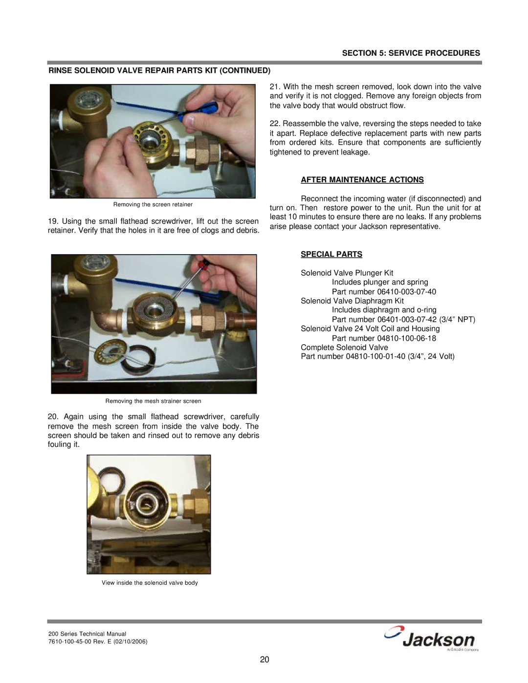
Removing the screen retainer
19.Using the small flathead screwdriver, lift out the screen retainer. Verify that the holes in it are free of clogs and debris.
21.With the mesh screen removed, look down into the valve and verify it is not clogged. Remove any foreign objects from the valve body that would obstruct flow.
22.Reassemble the valve, reversing the steps needed to take it apart. Replace defective replacement parts with new parts from ordered kits. Ensure that components are sufficiently tightened to prevent leakage.
AFTER MAINTENANCE ACTIONS
Reconnect the incoming water (if disconnected) and turn on. Then restore power to the unit. Run the unit for at least 10 minutes to ensure there are no leaks. If any problems arise please contact your Jackson representative.
SPECIAL PARTS
Solenoid Valve Plunger Kit Includes plunger and spring Part number
Solenoid Valve Diaphragm Kit Includes diaphragm and
Part number
Part number
Part number
Removing the mesh strainer screen
20.Again using the small flathead screwdriver, carefully remove the mesh screen from inside the valve body. The screen should be taken and rinsed out to remove any debris fouling it.
View inside the solenoid valve body
200 Series Technical Manual
20